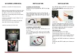
LOCATION & REMOVAL
Installation for OPV-2LR (CAN):
Installation has to be done behind the RADIO at the large
black plug.
Plug the black plug from the radio unit into the female
side of the supplied harness, then plug in the male side of
the supplied harness to the radio unit. Plug in and mount
the interface.
Installation for OPV-2LR (MOST)
Remove the GREEN plug from the GREEN socket on the
screen unit,
Plug the GREEN plug into the male green socket supplied,
next plug the supplied green female plug into the screen
unit, see below
INSTALLATION
Insert OPTICAL leads into OPV-2LR loom and car loom
AT THE SCREEN/RADIO to create a loop, see dia-
gram below
To remove the (out) fibre optic cable from the factory
connector you will need to remove the black outer cas-
ing and push out the blue locking insert. You will need
to do the same to insert the cable into the supplied
loom. (shown in diagram above)
Other Connections
Connect the RED cable to 12v+ PERM
Connect the BLACK cable to 12v- GROUND
Connect the BLUE cable to 12v+ to switch from factory
TV to your added source. Also see operating instruc-
tions.
Connect the cable AUDIO sockets to your audio source.
See fig 5
Connect the cable VIDEO socket to your video source,
see fig 5
INSTALLATION
Fig 2
Fig 1
Installation is made at the front monitor and radio.
Remove the radio surround trims and the radio top trim on
Sport, then pull forward the leather side trims that cover
the bottom screws of the air vents (circled below)
Remove the 4 screws holding the air vents and remove,
Remove the screen.
Access is now available to the rear of the radio to con-
nect the supplied loom.
On LR3 you may remove the radio by removing the 4
screws and unit above housing hazard button.
Locate the plug in the radio shown in fig 2.
INTERFACE
CAR CONNECTOR
OUT cable from screen
IN cable from interface
Fig 5


