4 | 9
Levels can now be taken at each coaxial output connector throughout the system, ie., at the end of
each cable and at the output of each passive (splitter/tap-off/outlet). These levels must be recorded
on a system block diagram or sketch. Levels can be referenced to either one microvolt or one millivolt,
whichever is more convenient. There is 60 dB difference between the dBuV and dBmV figures; all
drawings should indicate which reference is used. It is strongly recommended that readings be made
using a logarithmic dB scale, since confusion often arises when linear voltage readings are used.
When testing is complete, the cable and connector attenuation values should correspond to the
various signal level readings taken throughout the system. If a part of the system has higher than
calculated attenuation, the problem must be investigated and corrected. When this happens, levels
downstream from the correction point must be taken again, and recorded on the as-fitted drawings.
These final drawings are invaluable for future trouble shooting. Copies should be made for Naval
Tampa, the Ship-owner, and the Shipyard for future reference. Naval Tampa will archive such
drawings in hard copy and on electronic media where possible.
Typical problems:
Improper terminations: These will show up as a higher-than-calculated loss; they can be frequency
sensitive. They may also show as a short or open circuit if the termination is seriously corrupt.
Proper installer skills, hardware and tools are essential to a good working system. Factory Engineers
are available at reasonable cost to travel worldwide.
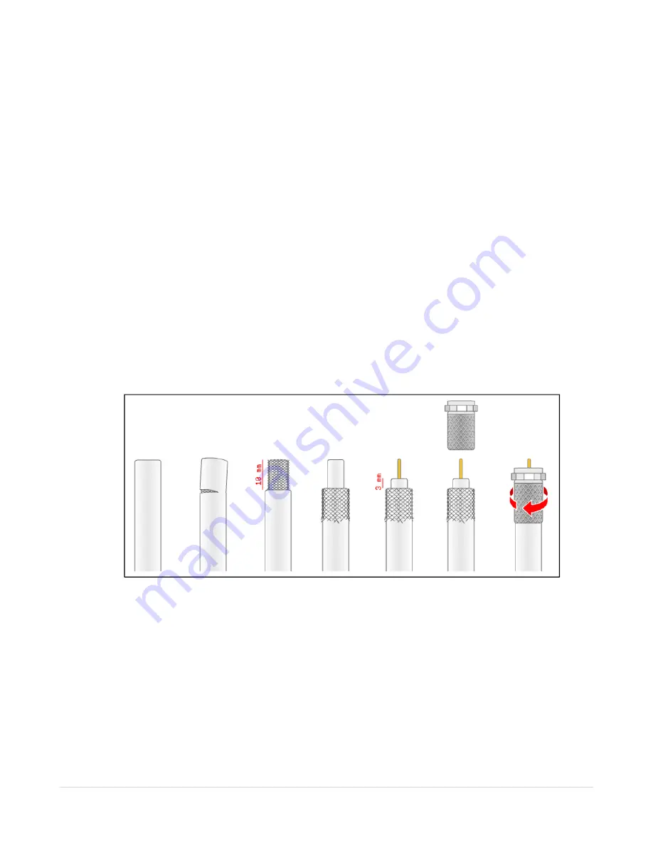
Stripping of coaxial cable for supplied twist on connectors.
Final Adjustments:
Before commencing any testing, ensure that the system is powered up and that the amplifier is active.
See the note on “Attenuators” in the Test Procedures section, above.
It is, of course, better to use testing and measuring equipment when available, such as a signal
generator and a frequency-selective voltmeter.
If no measuring equipment is available: Connect the antenna to the PR-4010 (Input and power). Use
a TV monitor attached to the 20dB test point on the PR-4900 (Output filter).


