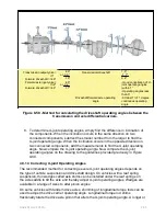
4.1.2 Driveline Phasing
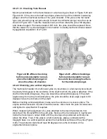
Heavy-duty U-joints have a unique characteristic. Because they are always operating at
an angle, they do not transmit constant torque or turn at a uniform speed during their
360-degree rotation (
Figure 8-48)
.
Figure 8-48 - A driveshaft will increase and decrease speed once each
revolution.
With the drive yoke turning at a constant rpm, a driveshaft increases and decreases
speed once each revolution. To counterbalance this fluctuation above and below mean
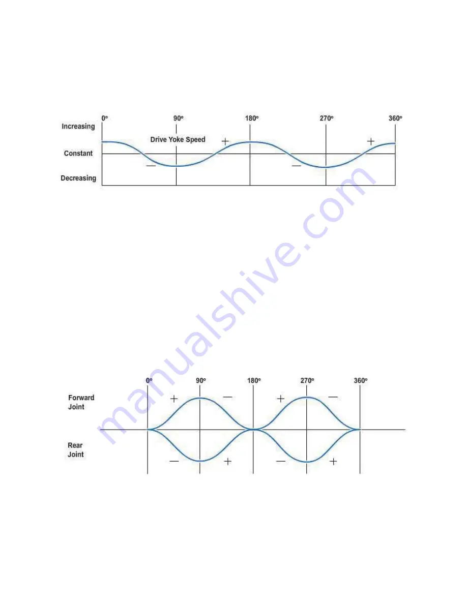
(average) driveshaft speed, the U-joints must be positioned in-phase with each other as
demonstrated in
Figure 8-49
. An out-of-phase condition produces an effect similar to
what occurs when two children are turning a rope, and the rope is snapped on one side;
by contrast, if the rope is snapped at both ends at the same time, the resulting waves
through the rope cancel each other, and neither child feels the reaction of the wave the
snap causes.
Figure 8-49 - Two universal joints in-phase will cancel out the speed
fluctuations in the driveshaft.
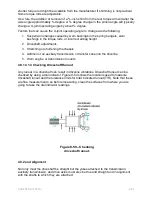
When in phase, the slip yoke lugs (ears) and welded yoke at the opposite end should be
perfectly in line as illustrated in
Figure 8-50
. If a driveshaft is assembled one spline out,
the driveshaft is out of phase and the result can be a significant vibration. There should
be opposing alignment arrows stamped on the slip yoke and on the tube shaft so you
NAVEDTRA 14050A
8-53


