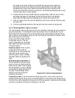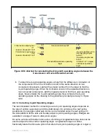
•
Pitting (small pits or craters in metal surfaces) is caused by corrosion and can
lead to surface wear and eventually failure.
•
Brinelling is a type of surface. Brinelling is often caused by improper installation
of the U-joints. Do not confuse the polishing of a surface (false-brinelling), where
no structural damage occurs, with actual brinelling. False-brinelling is a
manufacturing characteristic that surface-polishes bearing races without actually
creating any damage. Technicians should learn to recognize false-brinelling to
avoid replacing bearings that are functionally sound.
4.6.0 Yoke Inspection
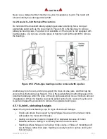
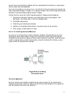
After removing the U-joint cross and bearing cups, inspect the yoke bores for damage
or burns. Some bore irregularities can be removed with a rat tail or half-round file,
followed by finishing with emery cloth.
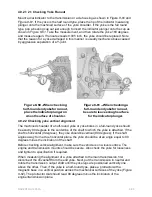
Check the yoke bores for wear, using a go-no-go wear gauge. Use an alignment bar (a
bar with approximately the same diameter as the yoke bore) to inspect for misalignment
of the yoke lugs. Slide the bar through both yoke bores simultaneously. If the alignment
bar will not pass through both yoke bores simultaneously, the yoke has been distorted
either by disassembly malpractice or excessive torque and should be replaced. Next,
clean and inspect the mating yoke with an alignment bar gauge. Do not risk reusing a
defective yoke.
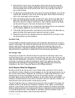
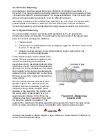
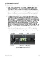
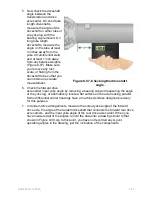
4.7.1 U-Joint Reassembly
Use the following procedure to assemble a driveshaft installing new U-joints.
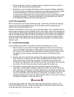
1. Place the slip yoke end of the driveshaft assembly in a bench vise so that you
can see the phase mark made on disassembly. Locate the phase mark on the
main section of the driveshaft and assemble mating the slip joint. Double check
the phasing. An out-of-phase driveshaft will cause an immediate driveline
vibration.
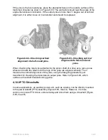
2. Remove the new U-joint from its packing and separate the bearing caps from the
cross trunnions. Visually inspect the cross, ensuring that the one-way check
valve in each trunnion lube hole is present. Then position the cross into the
driveshaft yoke aligning the lube zerk fitting as close as possible to the slip spline
lube fitting. The zerk fitting should be directed toward the inboard side.
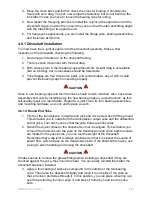
3. Paste some antiseize compound to the outside diameter of four bearing
assemblies. This facilitates installation and removal next time around. Angle the
cross and insert into the yoke. Fit the first bearing cup by inserting a trunnion into
the needle bearings, and then push the bearing cup into the yoke bore. When the
trunnion is inserted into the first bearing cup assembly, it is aligned. Insert the
opposing bearing cup into the yoke bore and press home. You can now insert the
lock tabs and fasteners, but do not torque yet.
CAUTION
If the bearing cap binds in the yoke bore, gently tap with a ball peen hammer in the
center of the bearing cap. Do not tap the outer edges of the bearing cap because this
could damage either the bearing cup or the yoke.
NAVEDTRA 14050A
8-60


