


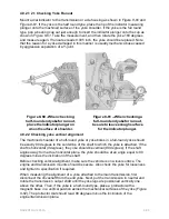

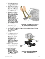


4. Next slide the U-joint over to the opposite side so that the trunnion exits the
bearing cup you have already installed by about half its length. Now align the
second bearing cup over the trunnion first, then in the yoke bore, and press
home until it is flush.
5. If a bearing cap assembly binds in the yoke bore during installation, you can tap
it lightly with a hammer in the center of the cap plate. Never strike the bearing
cup on the outer edges of the cap plate.
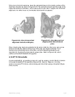
6. After both bearing cups have been seated in the yoke, put the lock plate tab in
place and insert the bolts into the yoke threads, turning them in first by hand,
then with a wrench. Torque to specification. Check that the bearing cup plates
are flush with the yoke. Then back the fasteners off slightly.
7. Install the zerk fitting(s) if you removed them and lubricate the U-joint assembly
until the grease appears to exit at all four trunnion seals.
8. Torque the bearing cap bolts to specification. Next, bend the lock plate tabs up
against the flat of the capscrew hex heads to lock them in place.
9. Repeat the process at the opposite end of the driveshaft. Do not forget to lube
the slip joint when you have finished.
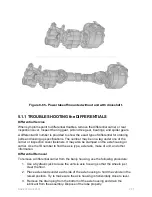
4.8.2 End Yoke
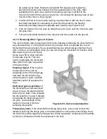
For driveshafts using half-round end yokes, first support the driveshaft more or less in
position using slings. Then install the bearing cups onto the cross trunnions. Install the
bearing cups into the end yoke shoulders and place the retaining straps over the
bearing assemblies. Thread the self-locking capscrews into the threaded holes and
torque the bolts to specification. Lubricate the cross and bearing assemblies.
4.8.3 Flange Yoke
Using slings to support the driveshaft, align the (permanent end) flange pilots of the
driveshaft, flange yoke, and drive axle companion flange with each other. Align the bolt
holes and then install bolts, lockwashers, and nuts to temporarily secure the driveshaft
to the axle. Compress the slip joint assembly to position the opposite end of the
driveshaft to the transmission companion flange. Align bolt holes and install bolts,
lockwashers, and nuts. Torque the fasteners to OEM specifications.
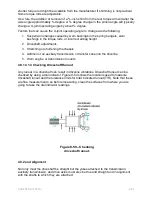
4.9.0 Chassis Vibration Diagnosis
Driveline vibrations are the source of many trouble cards, and some of them can be
very difficult to isolate. Vibration is not as apparent on the off-road equipment as it is on
the over-the-road vehicles. Operators are not likely to complain about vibration on off-
road equipment. When investigating the source of a driveline vibration, you always
should be aware that the cause can originate in an area other than in the driveline. It is
probably not good practice to rely solely on a driver's report of a driveline vibration, so
make it part of your normal routine to road test the vehicle.
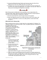
The first challenge is for you to determine the source of the complaint. The cause of a
vibration can be in the steering or suspension systems, in the engine or transmission
systems, in the wheels or tires. Road test the vehicle loaded and unloaded, if possible,
while recording engine rpm and road speed. Note any irregularities and at what engine
or road speeds they occur. If the problem is noticeable only when pulling a trailer, try
coupling to a different trailer to see if the problem persists.
NAVEDTRA 14050A
8-62


