


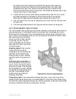
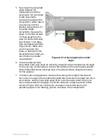
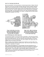

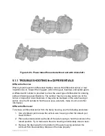


5. Now check the driveshaft
angle between the
transmission and drive
axle carrier. On short tube
length driveshafts,
measure the angle of the
driveshaft on either tube or
slip yoke lug with the
bearing cap removed. On
long tube length
driveshafts, measure the
angle on the tube at least
3 inches away from the
yoke circumferential weld
and at least 1 inch away
from any balance weights,
(
Figure 8-57
). Make sure
you remove any rust,
scale, or flaking from the
driveshaft tube so that you
can obtain an accurate
measurement.
6. Check the forward drive
Figure 8-57 - Checking the driveshaft
angle.
axle carrier input yoke angle by removing a bearing cap and measuring the angle
of the yoke lug, or alternatively, locate a flat surface on the axle housing parallel.
Some differential carrier housings have a machined surface designed precisely
for this purpose.
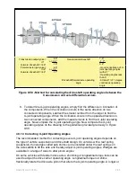
7. In tandem drive arrangements, measure the output yoke angle of the forward
drive axle, the angle of the tandem driveshaft that connects the forward rear drive
axle carriers, and the input yoke angle of the rear drive axle carrier. When you
have measured all of the angles, record the data onto a drawing similar to that
shown in
Figure 8-58
. Up to this point, you have not recorded any U-joint
operating angles in the drawing, just the inclination of the components.
NAVEDTRA 14050A
8-65


