


Transmission output yoke =
l3°
.0
Forward driveshaft = l4.9°
Forward axle input yoke =
l3.2°
Forward driveshaft = l4.9°
4.9°
or -3.0°
1.9°
4.9°
or -3.2°
1.7°
Transmission/driveshaft
1.9°
-1.7°
0.2°
-Good cancellation of U-
joint operating angles
(within 1°
-Operating angles less
than 3°
Driveshaft/forward axle operating
angle
-At least 1l of 1 degree
continuous operating
angle
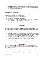
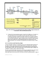
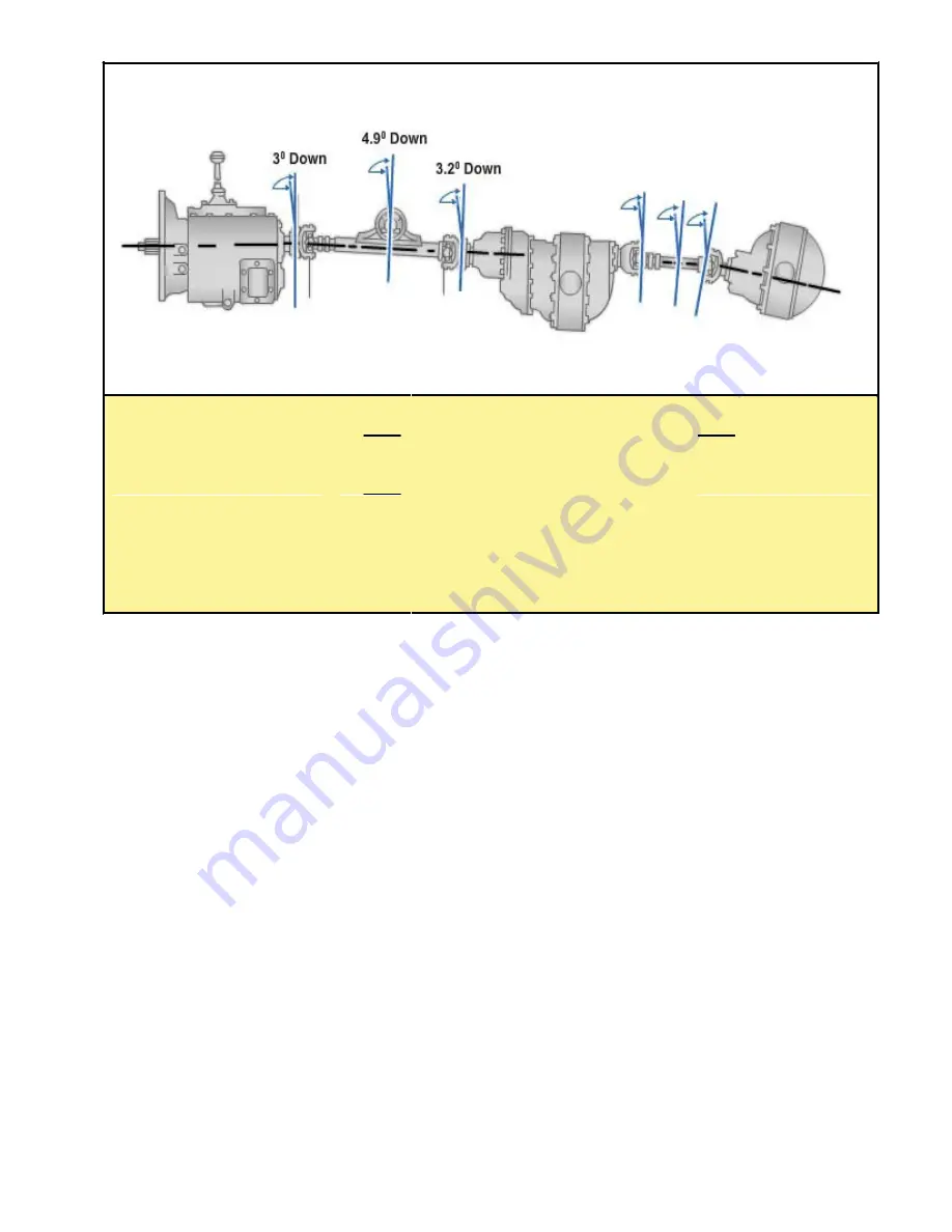
Figure 8-58 - Method for calculating the driveshaft operating angles between the
transmission and axle differential carriers.
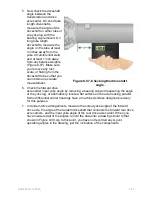
8. To determine U-joint operating angles, simply find the difference in inclination of
the components. When the inclination occurs in the same direction on two
connected components, subtract the smaller number from the larger to find the
U-joint operating angle. When the inclination occurs in the opposite direction on
two connected components, add the measurements to find the U-joint operating
angle. Now compare the U-joint operating angle. Now compare the U-joint
operating angles on the drawing to the guidelines provided previously in
Figure
8-58
.
4.9.1.3 Correcting U-joint Operating Angles
The recommended method for correcting severe U-joint operating angles depends on
the type of vehicle suspension and driveshaft design. On vehicles with a leaf spring
suspension, thin wedges called axle shims can be installed under the leaf springs on
the axle saddle to tilt the axle and thereby adjust U-joint operating angles. Wedges are
available in a range of sizes to alter pinion angles.
On some vehicles with tandem drive axles, shimming of longitudinal torque rods can be
used to adjust the drive carrier operating angle. Longitudinal torque rod shims
fractionally rotate the drive axle pinion that alters the U-joint operating angle. A longer or
NAVEDTRA 14050A
8-66


