3. Separate the case halves. Us a brass, plastic, or leather mallet to loosen the
parts.
4. Remove he differential spider (cross), four pinion gears, two side gears, and six
thrust washers from inside the case halves (
Figure 8-72
).
5. If the pinion and crown gearset is to
be replaced, remove the hardware
that holds the gear to the flange case
half as follows:
•
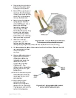
Carefully center punch each rivet
head in the center on the crown
gear side of the assembly.
•
Drill each rivet head on the ring
gear side of the assembly to a
depth equal to the thickness of one
rivet head. Use a drill bit that is
1/32-inch smaller than the body
diameter of the rivets (
Figure 8-
73
).
•
Drive the rivets through the holes
in the ring gear and flange case
half. Press from the drilled rivet
head.
CAUTION
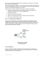
Figure 8-73 - Removing rivets
on a ring gear.
Do not remove the rivet heads or rivets
with a chisel and hammer because this
can damage the flange case half or
enlarge the rivet holes, resulting in loose
rivets.
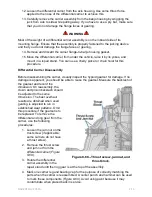
6. Separate the case half and ring gear
using a press. Support the assembly
under the ring gear with metal or
wooden blocks and press the case
half through the gear (
Figure 8-74
).
7. If the differential bearings need to be
replaced, remove the bearing cones
from the case halves. Use a bearing
puller or press to remove them.
Removing Drive Pinion and Bearing Cage
1.
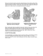
Fasten a yoke bar or flange bar to the
input yoke to prevent it from turning
while you remove the nut (
Figure 8-
75
).
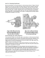
Figure 8-74 -
Pressing the
flange case half out of the
crown. gear.
2.
Remove the retaining nut from the drive pinion. Then remove the yoke or flange
bar.
NAVEDTRA 14050A
8-76

