3.
Turn the tie-rod cross tube in the direction necessary to bring toe to the specified
setting: turning the cross tube either lengthens or shortens it. After making the
adjustment, lower the vehicle to the floor. Measure the toe setting again.
4.
When the toe angle is set to specification, torque the tie-rod end clamp bolts to
specification.
CAUTION
Recheck the toe setting after any change in caster or camber angle.
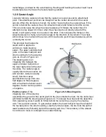
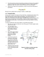
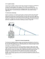
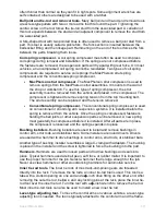
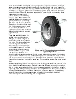
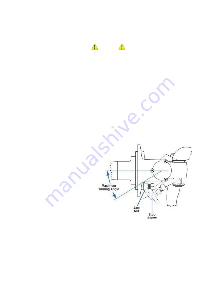
1.5.1 Turning Radius
Turning radius or angle is the degree of movement from a straight-ahead position of the
front wheels to either an extreme right or left position. Two factors limit the turning
angle: tire interference with the chassis and steering gear travel. To avoid tire
interference or bottoming of the steering gear, adjustable stop screws are located on the
steering knuckles (
Figure 9-8
). Turning radius or angle should be checked using the
radius gauge described earlier. If turning angle does not meet specifications, it should
be corrected.
To make an adjustment to the turning radius, use the following procedure:
1.
Block the rear wheels and raise the truck off the ground. Position support stands
under the front axle.
2.
Turn the wheels to the
extreme right turn until the
steering gear bottoms or
tire-to-chassis contact is
made.
3.
Back off the steering wheel
1/4
turn or until
�
- to 1-inch
clearance is obtained
between the tire and
chassis.
4.
Check both front tires for
clearance at full steering
lock. When the specified
clearance is set, back the
wheel stop screw out until
the screw contacts the axle
stop (
Figure 9-8
), and
tighten the jam nut.
5.
Repeat the same procedure
on the left extreme turn and
set the left steering knuckle
stop screw.
Figure 9-8 - Stop screw determines the
maximum turning angle.
NAVEDTRA 14050A
9-9