1.5.1 ving Front Axles
A stop screw is located on each end of the axle housing for the purpose of limiting the
amount of the turning angle of the wheels. These screws are not adjusted in
accordance with the frame and tire interference, as in conventional steer axles. The
stop screws in front drive axles limit the operating angle of the universal joints in the
drive axle shafts. You should reference the OEM service manual before making
adjustments.
1.5.2 Ackerman Geometry
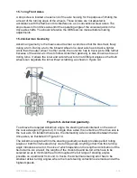
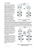
Ackerman geometry is the means used to steer a vehicle so that the tires track freely
during a turn. During a turn, the inboard wheel on a steer axle has to track a tighter
circle than the outer wheel. In other words, the outer tire has to travel just a little further
because of the wider arc it has to follow. Ackerman geometry is also known as toe-out
during turns. It allows the inner and outer wheel to turn at different angles so that both
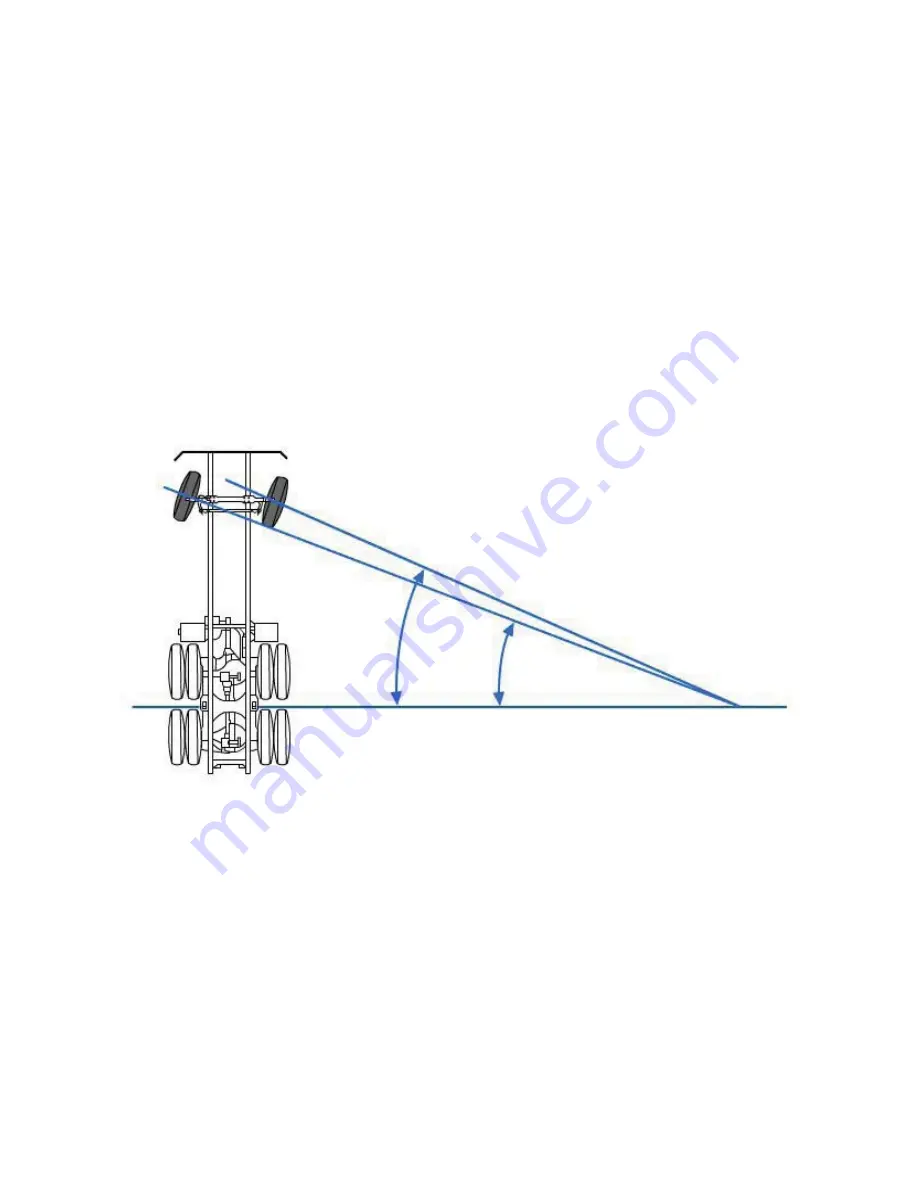
wheels can negotiate the turn without scrubbing, as shown in
Figure 9-9.
Figure 9-9 - Ackerman geometry.
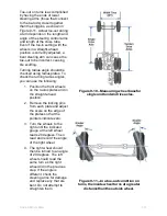
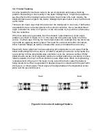
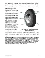
To achieve the required Ackerman angle, the steering wheels intersect on the axis of
the rear axle again (
Figure 9-9)
. On single drive axles, the centerline of the drive axle is
the rear axis. On tandem drive axles, the intersecting axle is centered between the two
drive axles, as illustrated in Figure 9-10.
The Ackerman angle built into the steering geometry actually provides perfect rolling
angles or both front wheels at only one turning angle. Anything other than this turning
angle introduces an error, the size of which depends on the length and inclination of the
tie-rod arms. As a result, the lengths of the cross tube and tie-rod arms have to be
selected so as to minimize the error throughout the full range of steering angles
possible on a particular front end. In trucks, the Ackerman steering error has to be
smallest at low turning angles, where the most steering corrections are made and at the
highest speeds.
NAVEDTRA 14050A
9-10

