

3.2.0 Setting up Alignment Equipment
The following are procedures for setting up electronic or light alignment equipment.
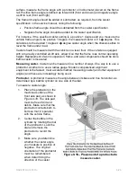
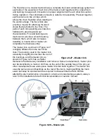
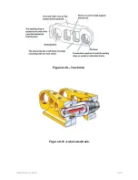
Installing the Alignment Head.
The alignment head consists of the electronic or light
assembly and the head frame assembly. The electronic assembly is free to turn in
relation to the head frame assembly, which is attached to the rim. A lock is used to
tighten the electronic assembly to the wheel or frame when necessary. Most alignment
heads are attached by clamping them on the inside of the rim. After the head is clamped
to the rim, safety straps are attached to the rim to keep the head from falling on the floor
and being damaged if the clamps slip. On some machines, alignment wires, called
strings, must be installed between the front and rear heads.
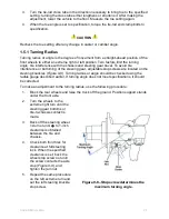
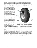
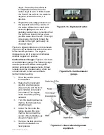
Compensating the Alignment.
All rims have some runout; therefore, there is no way to
install the alignment head without slight misalignment between the rim and head. This
runout must be removed to prevent inaccurate readings. The procedure to remove
runout may vary from one equipment manufacturer to another. With most types of
equipment, the procedure is to spin the wheel and rim
�
turn again and repeat the
procedure.
Most computerized alignment machines use lights on the head or readouts on the
screen to tell you when the head is properly compensated. Repeat the procedure for all
wheels. When all four wheels are compensated, the screen will give a set of alignment
readings. Since the wheels are off the ground, disregard the readings at this time.
CAUTION
Never allow the rim and head assembly to turn after it has been compensated. Any
movement from the vertical (straight up and down) position will affect readings.
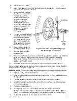
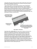
Lowering the Vehicle.
Before lowering the vehicle, make sure the turning plates are
centered under the wheels and remove the turntable locking pins. Apply the parking
brake firmly and then lower the vehicle. When the vehicle is resting on the turning
plates, bounce it at the front and rear bumpers. This will take any tension out of the
suspension parts and allow the vehicle to settle to its normal resting position.
Centering the Steering Wheel.
If the vehicle has power steering, start the engine and
allow it to idle. Then turn the steering wheel from side to side several times to equalize
play in the steering linkage. Then, center the steering wheel. Turn the engine off, if
necessary. It is not necessary to install the wheel-holding tool. However, you will need
this tool later during the alignment procedure.
Locking Brakes.
Lock the brakes with a brake pedal depressor. This prevents
excessive wheel movement while checking caster. At this time, you should firmly apply
the parking brake. If the vehicle has an automatic transmission, shift it into park.
3.3.0 Measuring Alignment
After all preliminary steps have been completed, the alignment can be measured. This
should be done in the order given in the following:
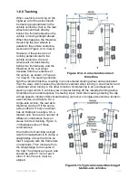
Checking Camber and Toe.
If the alignment machine has a display screen, front and
rear camber and toe will be shown on the screen. On most machines, this is an
automatic process once the heads have been compensated. On older alignment
machines using lighted heads, the front camber and toe will be shown by the position
NAVEDTRA 14050A
9-23


