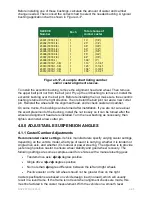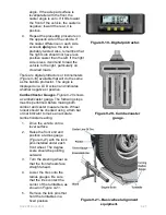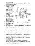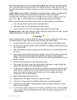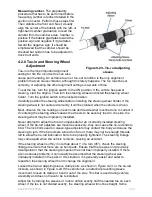
Before installing one of these bushings, calculate the amount of caster and camber
change needed. Then consult the correct chart to select the needed bushing. A typical
bushing application chart is shown in
Figure 9-17
.
SLEEVE
Number
Each
Total change of
camber caster
23001 (7979-1/8)
1
.13°
(1/8°)
23002 (7979-1/4)
1
.25°
(1/4°)
23003 (7979-3/8)
1
.38°
(3/8°)
23004 (7979-1/2)
1
.50°
(1/2°)
23005 (7979-5/8)
1
.63°
(5/8°)
23006 (7979-3/4)
1
.75°
(3/4°)
23007 (7979-7/8)
1
.88°
(7/8°)
23008 (7979-1)
1
1.00°
(1°)
23009 (7979-1-1/8)
1
1.13°
(1-1/8°)
23010 (7979-1-1/8)
1
1.25°
(1-1/4°)
23011 (7979-1-1/8)
1
1.38°
(1-3/8°)
23012 (7979-1-1/8)
1
1.50°
(1-1/2°)
Figure 9-17 - A sample chart listing camber
and/or caster alignment sleeves.
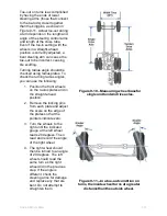
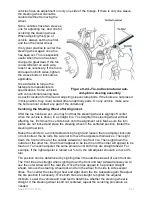
To install the eccentric bushing, remove the alignment head and wheel. Then remove
the upper ball joint nut from the ball joint. Pry up the old bushing to remove it. Install the
eccentric bushing over the ball joint. Before reinstalling the nut, make sure the eccentric
bushing is turned in the right direction. Then reinstall the ball joint nut and a new cotter
pin. Reinstall the wheel and the alignment head, and recheck caster and camber.
On some trucks, the bushing can be turned after installation. If you are not sure about
the exact placement of the bushing, install the nut loosely so it can be turned after the
wheel and alignment head are reinstalled. Turn the new bushing as necessary, then
tighten and install a new cotter pin.
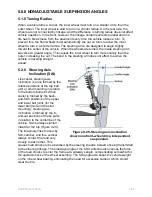
4.0.0 ADJUSTABLE SUSPENSION ANGLES
4.1.1 Caster/Camber Adjustments
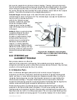
Recommended caster settings.
Vehicle manufacturers specify varying caster settings,
depending on the vehicle model, what type of load it is carrying, whether it is tandem or
single drive axle, and whether it is manual or power steering. The objective is to provide
just enough positive caster to ensure wheel stability and good wheel recovery. The
following settings are some examples used for vehicles with a manual steering gear:
•
Tandem drive axle:
�
-1
�
degree positive
•
Single drive: 1
�
-2
�
degrees positive
•
No more than
�
degree difference between the left and right wheels
•
Positive caster on the left wheel should not be greater than on the right
Caster specifications are based on vehicle design load (no load), which will usually
result in a level frame. If the frame is not level when alignment checks are made, this
must be factored in the caster measurement. With the vehicle on a smooth, level
NAVEDTRA 14050A
9-25

