2.2.0 Planetary Gears
Planetary gears are used in the automatic transmission as a basic means of multiplying
the torque from the engine. The name is derived from the physical arrangement of the
gears. They are always in mesh and thus cannot "clash" like other gears that go in and
out of mesh. The gears are designed so that several teeth are in mesh or in contact at
one time. This distributes the forces over several teeth at one time for greater strength.
Because the shafts generally used with planetary gear trains can be arranged on the
same centerline, a compact system can be obtained.
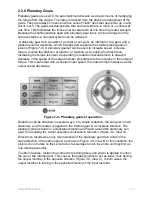
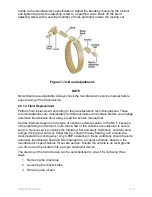
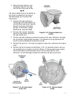
A planetary gear train consists of a center or sun gear, an internal or ring gear, and a
planetary carrier assembly, which includes and supports the smaller planet gears or
pinions (
Figure 7-9
). A planetary gearset can be used to increase speed, increase
torque, reverse the direction of rotation, or function as a coupling for direct drive.
Increasing the torque is known as operating in reduction because there is always a
decrease in the speed of the output member proportional to the increase in the output of
torque. This means that with a constant input speed, the output torque increases as the
output speed decreases.
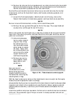
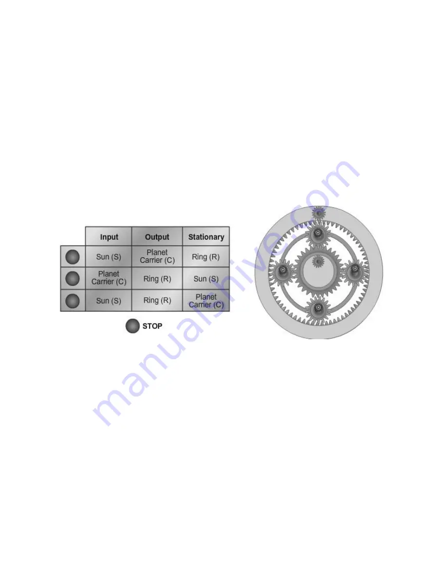
Figure 7-9 - Planetary gearset operation.
Reduction can be obtained in several ways. In a simple reduction, the sun gear is held
stationary, and the power is applied to the internal gear in a clockwise direction. The
planetary pinions rotate in a clockwise direction and "walk" around the stationary sun
gear, thus rotating the carrier assembly clockwise in reduction (
Figure 7-9, View A
).
Direct drive results when any two members of the planetary gear train rotate in the
same direction at the same speed, as shown in
Figure 7-9, View B
. In this condition, the
pinions do not rotate on their pins but act as wedges to lock the entire unit together as
one rotating assembly.
To obtain reverse, restrain the carrier from turning freely and power is applied to either
the sun or the internal gear. This causes the planet pinions to act as idlers, thus driving
the output member in the opposite direction (
Figure 7-9, View C
). In both cases, the
output member is turning in the opposite direction of the input member.
NAVEDTRA 14050A
7-10


