
engine. The process of multiplying engine torque through the converter has begun. If
the counterclockwise spinning oil was allowed to continue to the section of the pump
member, the oil would strike the blades of the pump in a direction that would hinder its
rotation and cancel any gains obtained in torque. To prevent this, a stator assembly is
added.
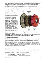
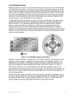
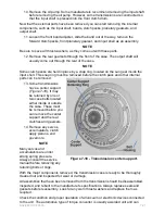
The stator is located between the pump and the turbine and is mounted on a one-way
or roller clutch, which allows it to rotate clockwise but not counterclockwise. The
purpose of the stator is to redirect the oil returning from the turbine and change its
direction of rotation back to that of the pump member. The energy of the oil is then used
to assist the engine in turning the pump. This increases the force of the oil, driving the
turbine, and as a result, multiplying the torque. The force of the oil flowing from the
turbine to the blades of the stator tends to rotate the stator counterclockwise, but the
one way roller clutch prevents this from happening.
With the engine operating at full throttle, the transmission in gear and the vehicle
standing still, the torque converter is capable of multiplying engine torque by
approximately 2:1. As turbine and vehicle speed increase, the direction of the oil leaving
the turbine changes. The oil flows against the rear side of the stator vanes in a
clockwise direction. Since the stator is now impeding the smooth flow of oil, its roller
clutch automatically releases, and the stator revolves freely on its shaft. Once the stator
becomes inactive, there is no further multiplication of engine torque within the converter.
At this point, the converter is merely acting as a fluid coupling as both the converter
pump and the turbine are turning at the same speed or at a 1:1 ratio.
2.4.1 Hydraulic System Operation
The hydraulic system has five basic functions:
1. The planetary holding devices are all actuated by hydraulic pressure from
hydraulic slave systems.
2. It keeps the torque converter charged with fluid at all times.
3. The shifting pattern is controlled by the hydraulic system by switching hydraulic
line pressure to programmed shifting devices according to vehicle speed and
load.
4. It circulates the oil through a remote oil cooler to remove excess heat that is
generated in the transmission and torque converter.
5. The hydraulic system provides a constant supply of lubricating oil to all critical
wearing surfaces of the transmission.
A hydraulic system requires a source of clean hydraulic fluid and a pump to pressurize
the fluid. The oil is drawn through the strainer from the transmission sump. The pump
drive gear is geared or keyed to the driven member of the torque converter; therefore,
whenever the engine is in operation, the pump is functioning. As the pump drive gear
rotates, it rotates the pump-driven gear, causing the oil to be lifted from the sump into
the oil pump. As the pump gears turn, oil is carried past the crescent section of the
pump. Beyond the crescent, the gear teeth begin to come together again, forcing the oil
out of the pump and into the hydraulic system under pressure. At this point, the oil is
delivered to the pressure control system.
NAVEDTRA 14050A
7-12


