


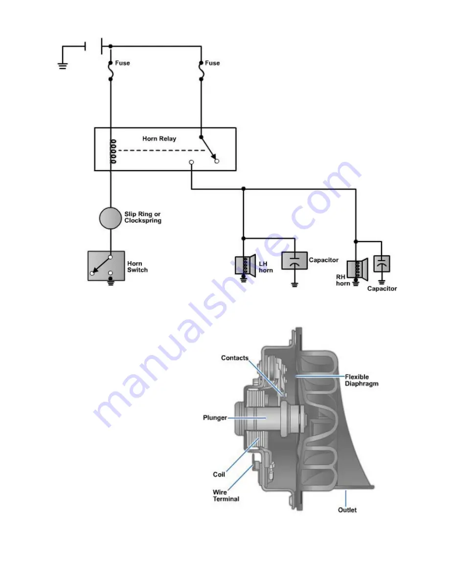
Figure 6-62 - Horn circuit.
When the driver presses the horn
button, the wire leading from the
horns is grounded. This causes
current to flow through the fuse
and horns. The resistance in the
horn coils limits how much current
flows into ground.
When the driver releases the horn
button, a spring pushes the
switch back open. This breaks or
disconnects the ground circuit. No
current can then flow through the
horns and they stop sounding.
Horn nomenclature.
A cutaway
view of a typical horn is given in
Figure 6-63
. It is made up of the
following components:
1. Horn coil - set of windings
that produce magnetic field
when energized by current
flow
Figure 6-63 -
Cutaway view of a horn.
NAVEDTRA 14050A
6-60


