background image

| 7

About your AIS/VHF antenna splitter | 

NSPL-500 User Manual

 Warning:

 This AIS/VHF antenna splitter must not be used 

with Class A transceivers, Aids to Navigation transceivers or AIS 
base stations.

What’s in the box?

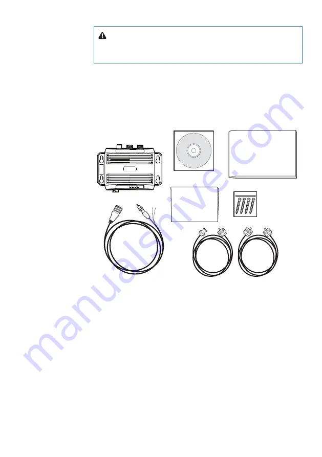
Figure 1 shows the items included with your NSPL-500 purchase. 
The following sections give a brief overview of each item. Please 
ensure all items are present and if any of the items are not present 
contact your dealer.

Fig. 1  What’s in the box

Accessory cables (x2)

Screws

(packet of 4)

Product manual

NSPL-500

Power and FM Radio cable

Product CD

Warranty

information

Figure 1 Items included with the product

• 

Product manual
The product manual is this document and should be read thor-
oughly prior to any attempt to install or use the NSPL-500. 

• 

VHF radio connection cable
This cable is used to connect a VHF radio to the NSPL-500. The cable 
has PL259 connectors at either end and requires a SO239 connector 
on the VHF radio. If your VHF radio does not have a SO239 connec-
tor please contact your dealer for details of suitable adaptors. 

• 

AIS transceiver connection cable
This cable is used to connect a Class-B AIS transceiver, such as the 
NAIS-500 to the NSPL-500. The cable has a BNC connector at one 

Summary of Contents for NSPL-500

Page 1: ...ENGLISH NSPL 500 AIS VHFantennasplitter User Manual www bandg com www simrad yachting com www lowrance com NSPL 500 ...

Page 2: ......

Page 3: ...en translated from another language Translation In the event of any conflict between any Translation of the Documentation the English language version will be the official version of the Documentation This manual represents the product as at the time of printing Navico Holding AS and its subsidiaries branches and affiliates reserve the right to make changes to specifications without notice Copyrig...

Page 4: ...isposal of this product and packaging 6 About your AIS VHF antenna splitter 6 About AIS 7 What s in the box 8 Electrical connections 9 Installation 9 Preparing for installation 9 VHF antenna 9 VHF radio 10 AIS transceiver 10 FM radio 10 Power cable 10 Installation procedures 16 Operation 16 Indicator functions 17 Troubleshooting 18 Specifications ...

Page 5: ... installation configuration 11 Figure 4 NSPL 500 dimensions 12 Figure 5 NSPL 500 mounting 12 Figure 6 Position of the VHF antenna connector 13 Figure 7 Position of the VHF radio connector 14 Figure 8 Position of the AIS transceiver connector 15 Figure 9 Connecting the power supply and optional FM output 16 Figure 10 Indicator location on the NSPL 500 unit ...

Page 6: ... compass safe distance of this unit is 0 3 m RF emissions notice The information provided in this section assumes the NSPL 500 is connected to an AIS Class B transceiver The warnings regarding RF emissions provided in the manual for the VHF radio being used with the NSPL 500 should also be noted prior to installation of the NSPL 500 Note The NSPL 500 generates and radiates radio frequency electro ...

Page 7: ... are shielded from the an tenna field by a grounded metallic barrier The antenna should not be co located or operated in conjunction with any other transmit ting antenna The required antenna impedance is 50 ohms Warranty This product is supplied with standard warranty as defined in the accompanying warranty information Warning Any attempt to tamper with or damage the product will invalidate the wa...

Page 8: ...rnational voyages and certain types of passenger vessels under the SOLAS mandate Class B transceivers Similar to class A transceivers in many ways but are normally lower cost due to the less stringent performance requirements Class B transceivers transmit at a lower power and at a lower reporting rate than class A transceivers AIS base stations AIS base stations are used by Vessel Traffic Sys tems...

Page 9: ...uct manual NSPL 500 Power and FM Radio cable Product CD Warranty information Figure1Itemsincludedwiththeproduct Product manual The product manual is this document and should be read thor oughly prior to any attempt to install or use the NSPL 500 VHF radio connection cable This cable is used to connect a VHF radio to the NSPL 500 The cable has PL259 connectors at either end and requires a SO239 con...

Page 10: ...ting holes are located as shown in Figure 2 Please refer to the Installation procedure section for details of how to mount the NSPL 500 Power and FM cable The power and FM cable connects to the NSPL 500 and enables connection to power and an FM radio antenna input Electrical connections The NSPL 500 has the following electrical connections as shown in Figure 2 Power supply VHF antenna connector VH...

Page 11: ...3 device Figure3Typicalinstallationconfiguration In addition to the items provided with your NSPL 500 the following items will be required for installation VHF antenna Connection to a suitable VHF antenna will be required for the NSPL 500 to operate A standard marine band VHF antenna such as that used with VHF voice radios will be sufficient Please take note of the warnings in section 1 regarding ...

Page 12: ...of your NSPL 500 please ensure you have the necessary additional items as detailed in the previous sec tion Preparing for installation It is strongly recommended that you read all of the instructions in this manual prior to installation If after reading this manual you are unsure about any element of the installation process please contact your dealer for advice The following sections explain the ...

Page 13: ... to spray or submersion It is acceptable to mount the NSPL 500 either vertically or horizon tally The VHF antenna splitter must be installed in a below decks envi ronment The NSPL 500 should be mounted in a location where the indicators are readily visible as these provide important information on the status of the NSPL 500 Fig 4 Dimensions 151 5mm 132 5mm 98mm 47mm 53mm Figure4NSPL 500dimensions ...

Page 14: ...Figure 6 A standard marine band VHF antenna or AIS antenna should be used with the NSPL 500 The connector type on the NSPL 500 is SO239 Your chosen VHF antenna requires a PL259 connector to mate with this If your VHF antenna does not use this type of con nector please contact your dealer for details of available adaptors Fig 6 Location VHF AIS Transceiver VHF Radio VHF Antenna Figure6Positionofthe...

Page 15: ...onnect to the VHF radio connector on the NSPL 500 as shown in Figure 7 If the cable supplied is not long enough please contact your dealer for details of suitable extension cables A standard marine band VHF voice radio should be used with the NSPL 500 The antenna splitter is DSC compatible Fig 7 Location VHF Radio AIS Transceiver VHF Radio VHF Antenna Figure7PositionoftheVHFradioconnector ...

Page 16: ...L 500 as shown in Figure 8 If the cable supplied is not long enough please contact your dealer for details of suitable extension cables A fully approved marine AIS class B transceiver such as the NAIS 500 or AIS receiver should be used with the NSPL 500 and requires a SO239 VHF antenna connector to connect to the NSPL 500 using the supplied accessory cable Fig 8 Location AIS AIS Transceiver VHF Ra...

Page 17: ...1A fuse block 1 Connect the red wire to the power supply positive terminal 2 Connect the black wire to the supply negative terminal 3 Connect the FM connector to the FM radio antenna input Fig 9 Power and FM Power in Power in FM output FM ground Green White Red Black FM ground Blue Figure9ConnectingthepowersupplyandoptionalFMoutput Note If the FM connector is not used please ensure the connector i...

Page 18: ...s to transmit simultaneously using a single VHF antenna When talking on the VHF radio AIS position reports are not transmitted Indicator functions The NSPL 500 includes three colored indicators as shown in Figure 10 The state of the indicators provides information regarding the status of the NSPL 500 Fig 10 Indicator lights Indicator lights Green Power Red Error Green AIS Green VHF Figure10Indicat...

Page 19: ...k the antenna output of the AIS transceiver is connected to the antenna splitter input labelled AIS Clicks or pops are heard from a connected FM broadcast receiver This is normal and may occur during VHF or AIS transmission VHF or AIS transmission range is reduced A small reduction in transmission range is normal and due to the insertion loss of the antenna splitter Both the AIS and VHF indicators...

Page 20: ...A at 12 VDC VHF and AIS frequency range 156 MHz to 162 MHz Insertion loss AIS VHF receive paths 0 dB 0 dB Insertion loss AIS VHF transmit paths Typical 1 dB Max input power AIS port 12 5 W Max input power VHF port 25 W Min input power VHF port 0 5 W AIS VHF and Antenna port impedance 50 Ohms FM port impedance 75 Ohms Operating temperature 15ºC to 55ºC Ingress protection IP67 6 ...

Page 21: ... 19 Specifications NSPL 500 User Manual NOTES ...

Page 22: ...20 Specifications NSPL 500 User Manual NOTES ...

Page 23: ......

Page 24: ... 988 11241 001 201 0318 NSPL 500 Product Manual www bandg com www simrad yachting com www lowrance com ...

Reviews: