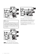
22 Installing the System Piping
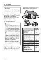
WARNING
Ɣ
Immediately repair any leaks in the system plumbing
to avoid adding make-up water. Make-up water adds
oxygen and minerals to the system that may lead to heat
exchanger failure.
Ɣ
Failure to follow these instructions may result in poor
performance, unnecessary wear of system components
and premature failure.
CAUTION
Do not solder piping directly onto the water connections,
as the heat may cause damage to internal components. Use
threaded water connections only.
4.1.2 Essential Elements in a Central Heating
System
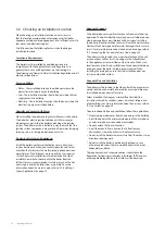
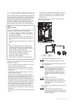
Auto Air Vent
The LCB700 boiler is equipped with an automatic air vent so that
the air from the boiler is automatically discharged. A separate
automatic air vent must be installed at the top of the piping
system to exhaust air from the entire piping system.
Expansion Vessel
An expansion vessel must be installed in the central heating
piping to prevent excessive pressure from building up in the
system.
The expansion vessel must be sized in accordance with the
water volume of the system as well as the firing rate of the
appliance.
Note
Ensure that the expansion vessel used is of sufficient
size for the system volume. Refer to BS 7074:1:1989
or The Domestic Heating Design Guide for sizing the
required vessel.
It is important to locate the expansion vessel and make-up
water connection, on the inlet side of any pump in the system,
as doing so will guarantee the lowest pressure in the system will
be at least equal to the vessel and make-up water pressure.
CAUTION
Ensure the expansion vessel cannot become isolated from
the boiler anytime the system is operating. Failure to follow
these instructions may lead to discharge from the pressure
relief valve, which may result in property damage or injury.
Pressure Relief Valve
The requirements recommended for the pressure relief valve are
as follows:
Ɣ
The pressure relief valve is calibrated to be activated at a
maximum pressure of 3 bar, and all the pipes and connections
must therefore be able to withstand pressures of up to 3 bar.
Ɣ
It must tilt in a downstream direction throughout its entire
length, and the water must run off to a suitable drain. It must
be positioned so as not to cause damage to cabling, electrical
equipment or persons.
Ɣ
The pressure relief discharge pipe must not be located above
a window, entry door or any other public access point. Bear
in mind that boiling water or steam could come out when
operating.
4.1.3 Central Heating System Piping
When connecting the central heating system, follow these
guidelines:
Ɣ
Carefully tighten all connections to avoid damage to fittings.
Ɣ
After installing the boiler, check the central heating system's
operation and inspect for leaks.
Items
Unit
Model
21RS/RSX
21LS/LSX
28RS/RSX
28LS/LSX
36RS/RSX
36LS/LSX
ڹ
t 10°C
Flow
Rate
lpm
30.1
40.1
51.6
Head
m
4.3
7.0
11.1
ڹ
t 15°C
Flow
Rate
lpm
20.1
26.8
34.4
Head
m
2.1
3.5
5.2
ڹ
t 20°C
Flow
Rate
lpm
15.1
20.1
25.8
Head
m
1.2
2.0
3.0
ڹ
t 25°C
(Minimum)
Flow
Rate
lpm
12
16
20
Head m
0.9
1.2
1.7
0
0.1
0.2
0.3
0.4
0.5
0.6
0.7
0.8
0.9
1
1.1
1.2
0
5
10
15
20
25
30
35
40
45
50
ǻ
P [
b
a
r]
Flow [LPM]
.%$2TGUUWTG&TQR
LCB700 21K_Set
LCB700 28K_Set
LCB700 36K_Set
21 kW
28 kW
36 kW
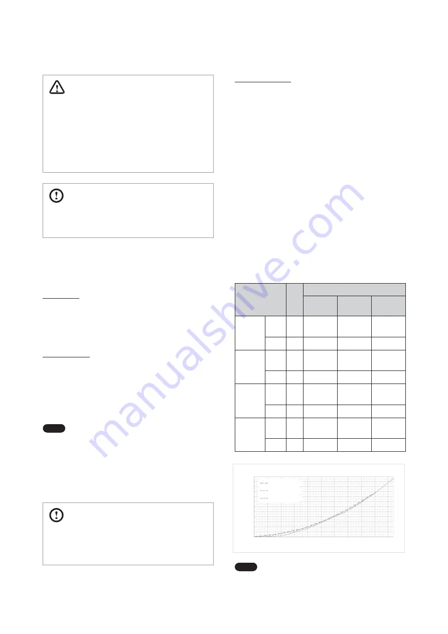
Note
Refer to the performance curve to select a pump
that suits your application. The boiler can supply up
to a maximum of 100 W current at the boiler pump
connection terminal.
Summary of Contents for LCB700-21LC
Page 78: ...78 Appendices 13 2 2 Burner Cover Flame Tube...
Page 92: ...Memo...
Page 93: ...Memo...
Page 94: ...Memo...
Page 95: ......

