Installing the System Piping 23
4.1.4 Water Quality Standards for Appliance
Quality Assurance
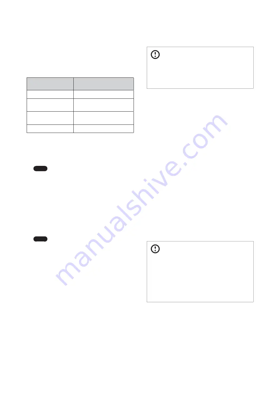
The water supplied to the boiler must satisfy the water quality
requirements on the following table.
Water Chemistry
Standards for Appliance Quality
Assurance
+DUGQHVV
Below 200 ppm
Chloride Concentration
Below 150 ppm
(Below 4 ppm of residual chlorine)
TDS
(Total Dissolved Solids)
Below 500 ppm
pH
6.5–8.5
Ɣ
The water hardness must be below 200 ppm.
Using water with a hardness above 200 ppm for the boiler
may create lime scale inside the boiler and cause a product
malfunction. Use a water softener to satisfy the standards for
appliance quality assurance (below 80 ppm is recommended).
Note
Using indirect heat exchange through a plate-
type heat exchanger is an exception.
Ɣ
The chloride concentration of water must be below 150
ppm (below 4 ppm of residual chlorine).
Using the water with a chloride concentration above 150
ppm or 4 ppm for residual chlorine for the boiler may cause a
product malfunction due to corrosion.
Ɣ
The pH must be between 6.5 and 8.5.
-
Using water with a pH below 6.5 may cause a product
malfunction due to corrosion.
-
Using water with a pH above 8.5 may cause a product
malfunction due to lime scale created inside the boiler.
Note
The following situations adversely impact the
quality of the appliance
Ɣ
The water supplied to the boiler does not satisfy the water
quality requirements in the table above.
-
Using chemically unbalanced water for the boiler may
cause a product malfunction or reduce the product
lifetime.
Ɣ
Water below the minimum circulation flow rate is supplied
to the boiler (to see detailed flow rate information, refer to
the “4.1.3 Central Heating System Piping” on page 22.
-
Using water that is below the minimum circulation flow
rate for the boiler may cause a product malfunction due to
the creation of lime scale inside the boiler or a reduction
in product efficiency. If the flow rate is lower than the
minimum rate, use an external pump (below 100 W) to
maintain a flow rate above the minimum. Also, ensure the
pipes used for the boilers are not blocked and check if
there are any pressure drops.
CAUTION
If the water supplied to the boiler does not satisfy the water
quality requirements, contact an authorised technician or
licensed professional to avoid product malfunctions due to
poor water quality before supplying water to the boiler.
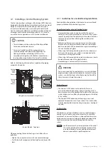
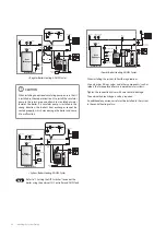
4.2 Installing a System Application
Refer to the following examples to properly implement a system
for central heating, DHW supply, or both. These examples
are provided to suggest basic guidelines when you installing
the boiler system. However, the actual installation may vary
depending on the circumstances, local building codes or
regulations.
The heating capacity of the unit must be previously established
by calculating the building’s heat requirement according to
the current regulations. To ensure proper operation and long
boiler life, the plumbing system must be adequately sized and
complete with all the necessary accessories, including a room
thermostat, a thermostatable valve (TRV), etc. The system
delivery and return pipes must have a diameter of at least 22
mm for the first 3 m of length from the unit.
If the system delivery and return pipes follow a path where air
pockets can form in certain places, it is advisable to install vent
valves at these points. Also, drain cocks must be installed at the
lowest points in the system to allow complete emptying.
An automatic bypass with a flow rate of at least 6 l/min must
be installed (as far away as possible from the boiler) if radiators
with thermostatic valves have been connected to combination
boilers and in front of any motorised valves for system/regular
boilers.
CAUTION
Ɣ
The installation must be made by sufficiently qualified
technicians, authorised to do so.
Ɣ
For correct installation, all the requirements and
recommendations described in the Regulation for
Heating Installations in Buildings (RITE) must be
complied with, together with all other national and/or
local regulations applicable at the time of installation.
Summary of Contents for LCB700-21LC
Page 78: ...78 Appendices 13 2 2 Burner Cover Flame Tube...
Page 92: ...Memo...
Page 93: ...Memo...
Page 94: ...Memo...
Page 95: ......

