background image

18 SMC CLOUD USER SETUP, REGISTRATION AND LOGIN

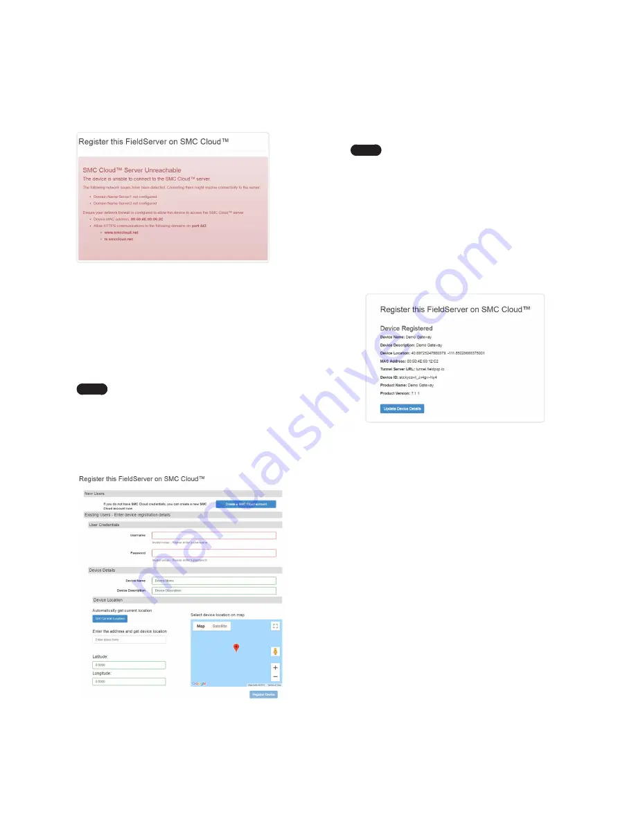
6.  To input the device location, do one of the following:


Enter the address in the address field.


Click the “Get Current Location” button to auto-populate.

Note

This button will only work if location services 

have been enabled on the local browser. If using 

the Chrome browser and connected via LAN, this 

method will not work.


Drop a location directly on the Google map.


Enter the latitude and longitude manually.

7.  Click Register Device.

8.  Once the device has successfully been registered, the following 

screen will appear listing the device details and additional 

information auto-populated by the gateway.

Figure 30: Device Registered for SMC Cloud

4.  If the gateway cannot reach the SMC Cloud server, the 

following message will appear.

Figure 28: SMC Cloud Connection Problems Message


Follow the directions presented in the warning message and 

check that the DNS settings are set up with the following 

Domain Name Server (DNS) settings: 

DNS1=8.8.8.8 

DNS2=8.8.4.4


Ensure that the gateway is properly connected to the 

Internet.

Note

If changes to the network settings are done, 

remember to click “Update IP Settings” and then 

power cycle the gateway.

5.  On the registration page, fill in user credentials and all other 

device information fields for registration of each individual 

gateway in the field.

Figure 29: SMC Cloud Registration Page

Summary of Contents for LonWorks Gateway

Page 1: ...ay Start up Guide For Interfacing Navien Products To Building Automation Systems and SMC Cloud LonWorks APPLICABILITY EFFECTIVITY Explains LonWorks Gateway and how to install it The instructions are e...

Page 2: ...port to the field protocol cabling Section 4 3 5 Connect power to the gateway 6 pin connector Section 4 4 6 Use a web browser to access the gateway Web Configurator page to select the profiles of the...

Page 3: ...y Device Communications 14 7 HOWTO STARTTHE INSTALLATION OVER CLEARING PROFILES 15 8 COMMISSIONING GATEWAY ON A LONWORKS NETWORK 16 8 1 Commissioning Gateway on a LonWorks Network 16 8 1 1 Instruction...

Page 4: ...Switch on the Gateway 9 Figure 10 LonWorks Terminal 9 Figure 11 Required Current Draw for the Gateway 10 Figure 12 Power Connections 10 Figure 13 External Power Connections 10 Figure 14 Ethernet Port...

Page 5: ...xtensive product certification standards and tests to provide the integrator and user with confidence that products from multiple manufacturers utilizing LonMark devices work together Sierra Monitor h...

Page 6: ...the optional DIN rail bracket Use of any other screws may damage the unit Gateway Connectivity Diagram The gateway can connect with Sierra Monitor s SMC Cloud The SMC Cloud allows technicians the OEM...

Page 7: ...igure 2 Supported Point Count Capacity Devices Registers Per Device NFB Single Boiler 118 NFB Main 1 Sub 1 Sub 31 113 1013 Figure 3 Registers per Device 3 SETUP FOR GATEWAY 3 3 Configuring Device Comm...

Page 8: ...hrough 6 are for power Do not connect power until Section 4 4 1 2 O N ON 1 2 A B G 3 Pin Terminal Block 6 Pin Phoenix Connector 1 2 O N ON 1 2 Tx Rx GND PWR PWR FRAME GND Boiler front panel Gateway Pi...

Page 9: ...RS 485 Biasing Switch on the Gateway 4 2 2 End of LineTermination Switch for the RS 485 Device Network On long RS 485 cabling runs the RS 485 trunk must be properly terminated at each end The gateway...

Page 10: ...cal 210 mA 130 mA 90 mA GXXX001933 Maximum 250 mA 170 mA 110 mA Note These values are nominal and a safety margin should be added to the power supply of the host system A safety margin of 25 is recomm...

Page 11: ...s assign a static IP Address to the PC on the 192 168 1 xxx network For Windows 10 1 Find the search field in the local computer s taskbar usually to the right of the windows icon and type in Control...

Page 12: ...12 USE THE GATEWAY WEB CONFIGURATOR TO SETUP THE GATEWAY This Page Intentionally Left Blank...

Page 13: ...username and password Note The default username is admin The default password is admin Figure 16 Login Window 4 From the Web App landing page Figure 17 click the Configure tab Figure 17 Web App Landin...

Page 14: ...Profiles are shown below the Configuration Parameters 2 The Active Profiles section lists the currently active device profiles including previous Web Configurator additions This list is empty for new...

Page 15: ...gurator 1 The Web Configurator is displayed as the landing page 2 At the bottom left of the page click the Clear Profiles and Restart button 3 Once restart is complete all past profiles discovered and...

Page 16: ...the PC on the 192 168 1 xxx network For Windows 10 1 Find the search field in the local computer s taskbar usually to the right of the windows icon and type in Control Panel 2 Click Control Panel clic...

Page 17: ...al splash page will appear click Close to view the registration page Figure 27 Registration Information Page 3 If a warning message appears instead of the splash page follow the suggestion that appear...

Page 18: ...ails and additional information auto populated by the gateway Figure 30 Device Registered for SMC Cloud 4 If the gateway cannot reach the SMC Cloud server the following message will appear Figure 28 S...

Page 19: ...n credentials Figure 31 SMC Cloud Login Page Note If the login password is lost see the SMC Cloud Start up Guide for recovery instructions On first login the Privacy Policy window will appear Read the...

Page 20: ...ver Toolbox to connect to the gateway 2 Click on Diagnostics and Debugging Button then click on view and then on connections 3 If there are any errors showing on the Connection page refer to Appendix...

Page 21: ...that support can quickly solve the problem There are two methods for taking diagnostic captures FieldServerToolbox This method requires installation of the FS Toolbox program A FS Toolbox diagnostic c...

Page 22: ...hoose Open to launch explorer and have it point directly at the correct folder c Send the diagnostic zip file to technical support Appendix A 5 2 Using FS GUI Diagnostic Capture via FS GUI is only ava...

Page 23: ...the Start button under the Full Diagnostic heading to start the capture When the capture period is finished a Download button will appear next to the Start button 5 Click Download for the capture to b...

Page 24: ...d is complete click on the System Restart button Appendix B 2 Securing Gateway with Passwords Access to the gateway can be restricted by enabling a password on the FS GUI Passwords page click Setup an...

Page 25: ...SH1 Thermostat input Status nvoSH1ThmInS_XXX SNVT_switch SH2 Thermostat input Status nvoSH2ThmInS_XXX SNVT_switch SH3 Thermostat input Status nvoSH3ThmInS_XXX SNVT_switch DHW call signal nvoDHW_ClSig_...

Page 26: ...XXX SNVT_count_f Total amount of gas nvoTotAmtGas_XXX SNVT_count_f Boiler On Off command nviBlOnOfCmd_XXX SNVT_count_f SH supply setpoint setting nviSHSupSPSt_XXX SNVT_temp_p SH return setpoint settin...

Page 27: ...NVT_switch Sub01 Error state nvo01ErrSt_XXX SNVT_switch Sub01 Boiler enable status nvo01BlEnSta_XXX SNVT_switch Sub01 Boiler pump op Status nvo01BlPmOpS_XXX SNVT_switch Sub02 Burner op state nvo02BrnO...

Page 28: ...8ErrSt_XXX SNVT_switch Sub08 Boiler enable status nvo08BlEnSta_XXX SNVT_switch Sub08 Boiler pump op Status nvo08BlPmOpS_XXX SNVT_switch Sub09 Burner op state nvo09BrnOpSt_XXX SNVT_switch Sub09 Frozen...

Page 29: ...Sub15 Boiler enable status nvo15BlEnSta_XXX SNVT_switch Sub15 Boiler pump op Status nvo15BlPmOpS_XXX SNVT_switch Sub16 Burner op state nvo16BrnOpSt_XXX SNVT_switch Sub16 Frozen protection mode nvo16F...

Page 30: ...Sub22 Boiler enable status nvo22BlEnSta_XXX SNVT_switch Sub22 Boiler pump op Status nvo22BlPmOpS_XXX SNVT_switch Sub23 Burner op state nvo23BrnOpSt_XXX SNVT_switch Sub23 Frozen protection mode nvo23F...

Page 31: ...nable status nvo29BlEnSta_XXX SNVT_switch Sub29 Boiler pump op Status nvo29BlPmOpS_XXX SNVT_switch Sub30 Burner op state nvo30BrnOpSt_XXX SNVT_switch Sub30 Frozen protection mode nvo30FrzPrMd_XXX SNVT...

Page 32: ...count_f Sub01 Operation Status nvo01OpStat_XXX SNVT_count_f Sub01 Main Error code nvo01MnErrCd_XXX SNVT_count_f Sub01 Current Heat capacity nvo01CurHtCp_XXX SNVT_lev_percent Sub01 Supply temperature n...

Page 33: ...nt_f Sub03 Total amount of gas nvo03TotGas_XXX SNVT_count_f Sub04 Operation Status nvo04OpStat_XXX SNVT_count_f Sub04 Main Error code nvo04MnErrCd_XXX SNVT_count_f Sub04 Current Heat capacity nvo04Cur...

Page 34: ...me_hour Sub06 Current amount of gas nvo06CurGas_XXX SNVT_count_f Sub06 Total amount of gas nvo06TotGas_XXX SNVT_count_f Sub07 Operation Status nvo07OpStat_XXX SNVT_count_f Sub07 Main Error code nvo07M...

Page 35: ...ub09 Total time of CH operation nvo09TotTmCH_XXX SNVT_time_hour Sub09 Current amount of gas nvo09CurGas_XXX SNVT_count_f Sub09 Total amount of gas nvo09TotGas_XXX SNVT_count_f Sub10 Operation Status n...

Page 36: ...2 Number of CH operation nvo12NmCH_Op_XXX SNVT_count_f Sub12 Total time of CH operation nvo12TotTmCH_XXX SNVT_time_hour Sub12 Current amount of gas nvo12CurGas_XXX SNVT_count_f Sub12 Total amount of g...

Page 37: ...after installation nvo15TotTmIn_XXX SNVT_count_f Sub15 Number of CH operation nvo15NmCH_Op_XXX SNVT_count_f Sub15 Total time of CH operation nvo15TotTmCH_XXX SNVT_time_hour Sub15 Current amount of gas...

Page 38: ...temperature nvo18ExhTmp_XXX SNVT_temp_p Sub18 Total time after installation nvo18TotTmIn_XXX SNVT_count_f Sub18 Number of CH operation nvo18NmCH_Op_XXX SNVT_count_f Sub18 Total time of CH operation nv...

Page 39: ...NVT_temp_p Sub21 Maximum Heat capacity nvo21MaxHtCp_XXX SNVT_count_f Sub21 Exhaust temperature nvo21ExhTmp_XXX SNVT_temp_p Sub21 Total time after installation nvo21TotTmIn_XXX SNVT_count_f Sub21 Numbe...

Page 40: ..._lev_percent Sub24 Supply temperature nvo24SupTmp_XXX SNVT_temp_p Sub24 Return temperature nvo24RetTmp_XXX SNVT_temp_p Sub24 Maximum Heat capacity nvo24MaxHtCp_XXX SNVT_count_f Sub24 Exhaust temperatu...

Page 41: ...rror code nvo27MnErrCd_XXX SNVT_count_f Sub27 Current Heat capacity nvo27CurHtCp_XXX SNVT_lev_percent Sub27 Supply temperature nvo27SupTmp_XXX SNVT_temp_p Sub27 Return temperature nvo27RetTmp_XXX SNVT...

Page 42: ...b30 Operation Status nvo30OpStat_XXX SNVT_count_f Sub30 Main Error code nvo30MnErrCd_XXX SNVT_count_f Sub30 Current Heat capacity nvo30CurHtCp_XXX SNVT_lev_percent Sub30 Supply temperature nvo30SupTmp...

Page 43: ...NVT_count_f Boiler setpoint in DHW operation nviBlSPDHWOp_XXX SNVT_temp_p Outdoor reset curve heatload setting nviOtRsCvHtS_XXX SNVT_count_f Maximum outdoor temperature setting nviMxOtTmpSt_XXX SNVT_t...

Page 44: ...d Access Area requiring a key or a special tool to gain access This device must not be connected to a LAN segment with outdoor wiring Appendix D 1 Specifications Gateway Part Number GXXX001933 Electri...

Page 45: ...have been removed or altered This Limited Warranty also will not apply to interconnecting cables or wires consumables or to any damage resulting from battery leakage In all cases Sierra Monitor Corpo...

Page 46: ...Memo...

Page 47: ...Memo...

Page 48: ...rmance data to LonWorks protocols For technical support please contact us at 800 519 8794 800 519 8794 www NavienInc com 20 Goodyear lrvine CA 92618 Installation Operation Manual LonWorks Gateway Star...

Reviews: