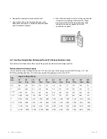
14.
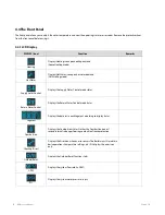
Place the PCB assembly back on to the boiler and tighten
the three screws.
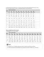
15.
Check the labels carefully and then connect all the wires.
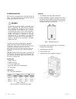
16.
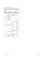
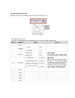
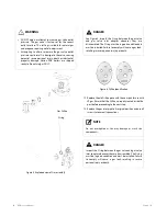
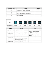
For LP, set DIP SW2 #2 to On. For NG, set DIP SW2 #3 to Off.
WARNING
Ensure that you have turned off the power to the boiler
before accessing the DIP switches.
DANGER
When conversion is required, be sure to set the Front
Panel DIP switches according to the supply gas type.
Failure to properly set the DIP switches could cause
carbon monoxide poisoning, resulting in severe
personal injury or death.
17.
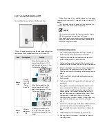
Turn on the gas and water supply to the boiler.
18.
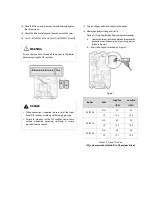
Measure and adjust the gas/air ratio.
Option 1. Using Combustion Analyzer (recommended)
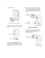
a.
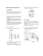
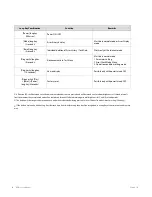
Loosen the screw, rotate the plate and remove the
gasket to access the emissions monitoring port as
shown in Figure 7.
b.
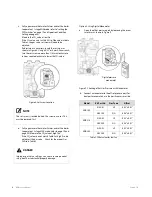
Insert the analyzer into the port (Figure 7).
Figure 7
Boiler
Fuel
High fire
Low fire
%CO
2
%CO
2
NCB-180
NG
8.9
9.5
LP
10.2
10.8
NCB-210
NG
8.9
9.5
LP
10.2
10.8
NCB-240
NG
8.9
9.5
LP
10.2
10.8
Table 2. CO
2
and CO value
(CO
2
values must be within 0.5% of the values listed.)
Summary of Contents for NCB-180
Page 3: ......
Page 16: ......
Page 135: ...132 NCB Service Manual Version 1 0 7 2 Burner Assembly...
Page 139: ...136 NCB Service Manual Version 1 0 7 4 Fan Gas Assembly...
Page 142: ...Memo...
Page 143: ...140 NCB Service Manual Version 1 0 Memo...
Page 144: ...Memo...
Page 145: ...142 NCB Service Manual Version 1 0 Memo...
Page 146: ...Memo...
Page 147: ...144 NCB Service Manual Version 1 0 Memo...
Page 148: ...Memo...


