54
Venting the Boiler
5.1 Selecting a Vent Type
All boilers are prepared at the factory to be direct vented (sealed combustion). Navien recommends direct air vent installations whenever
possible to avoid back drafting cold air through the boiler unit. If you cannot use a direct vent, ensure that an ample supply of make-up air is
available in the installation location.
Navien also recommends installing a new vent system with this appliance. If reusing an existing vent system, thoroughly inspect it for
punctures, cracks, or blockages prior to connecting it to the boiler.
Direct Venting
The boiler uses a 3 in or 4 in diameter exhaust and a 3 in or 4 in diameter air intake ducts. To ensure the draw of air directly from and exhaust of
air directly to the outside of the building, create an airtight seal from the boiler collar to the vent termination.
Intake materials can be made of ABS, PVC, CPVC, PP, galvanized steel, corrugated aluminum or any other such materials. If you use a
corrugated material, ensure that there is not inadvertent crimping of, or damage to, the intake air pipe.
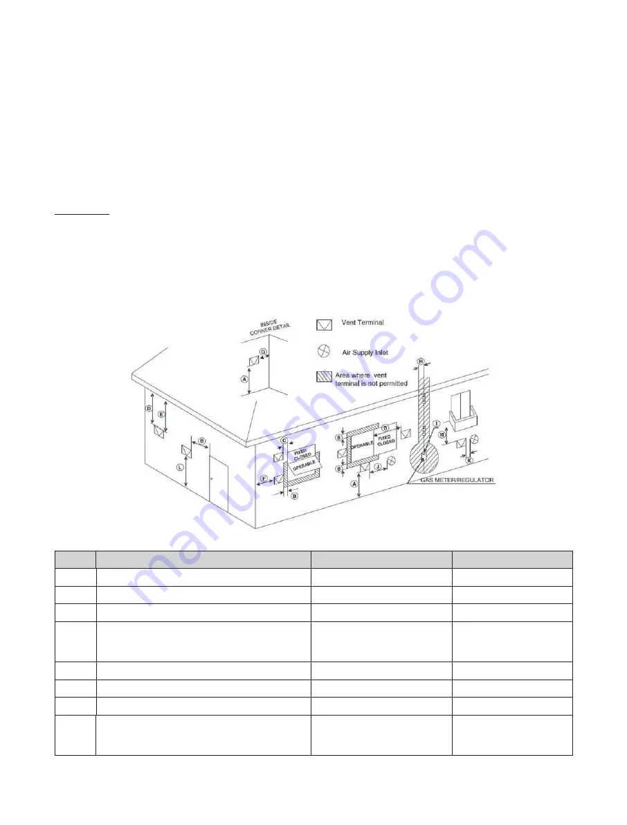
When using direct venting, maintain the following venting clearances, as required by
ANSI Z21.10.3 and the National Fuel Gas Code, ANSI
Z223.1/NFPA 54, and CAN/CGA B149.1 Natural Gas and Propane Installation Code:
Ref
Description
Canadian Direct Vent Installations
1
US Direct Vent Installations
2
A
Clearance above grade, veranda, porch, deck, or balcony
12 in (30 cm)
12 in (30 cm)
B
Clearance to window or door that may be opened
36 in (91 cm)
12 in (30 cm)
C
Clearance to permanently closed window
*
*
D
Vertical clearance to ventilated soffit located above the
terminal within a horizontal distance of 2 ft (61 cm) from
the center line of the terminal
*
*
E
Clearance to unventilated soffit
*
*
F
Clearance to outside corner
*
*
G
Clearance to inside corner
*
*
H
Clearance to each side of center line extended above
meter/regulator assembly
3 ft (91 cm) within a height
15 ft above the meter/regulator
assembly
*
Summary of Contents for NHB Series
Page 120: ...120 Appendixes 12 6 Component Assembly Diagrams and Part Lists 12 6 1 Case Assembly NFB 301C...
Page 122: ...122 Appendixes 12 6 2 Case Assembly NFB 399C...
Page 124: ...124 Appendixes 12 6 3 Heat Exchanger and Waterway Assembly NFB 301C...
Page 126: ...126 Appendixes 12 6 4 Heat Exchanger and Waterway Assembly NFB 399C...
Page 128: ...128 Appendixes 12 6 5 Combustion Parts Assembly NFB 301C...
Page 131: ...131 Appendixes 12 6 6 Combustion Parts Assembly NFB 399C...
Page 134: ...Memo...


