background image

15 

Cable shielding 

Ensure that all data cables are properly shielded that the cable shielding is intact (e.g. hasn’t been 
scraped off by being squeezed through a tight area). 

4.4


Power connection 

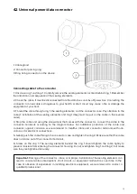
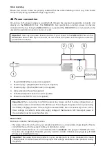
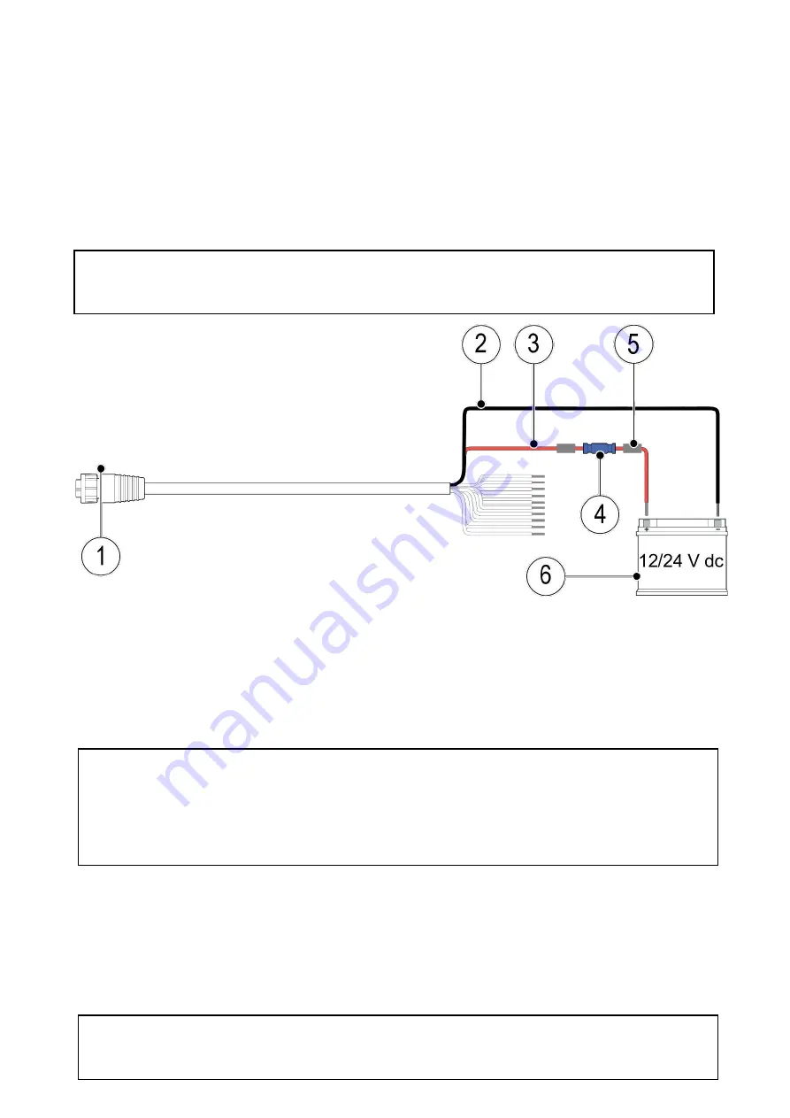
Connection to the power supply is possible both through the universal power/data connector and 
directly via the NMEA2000 bus. The NMEA2000 bus specification provides power for devices 
connected to the bus. If only the NMEA2000 bus is used and the NMEA0183 bus is not used, then the 
universal power/data connector can be not used. 

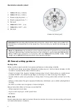
1.

Power/data M12 8-pin connector (supplied)

2. Power supply – (Negative) Black  wire (not supplied)
3. Power  (Positive) Red  wire (not supplied)
4. Inline waterproof fuse 2A (supplied)
5. Suitable waterproof connection (not supplied)
6. Power source (12/24 V  dc) (not supplied)

Power cable 

Ensure you observe the following advice: 
• The power cable for each unit in your system should be run as a separate, single length of 2-wire

cable from the unit to the vessel's battery or distribution  panel.

• For power cable extensions, it is recommended that a 

minimum 

wire gauge of 16 AWG (1.3 mm

2

).

For cable runs longer than 15 meters, you may need to consider a thicker wire gauge (e.g. 14 AWG

(2.1 mm

2

), or 12 AWG (3.3 mm

2

) ).

Important: 

Be aware that some products in your system (such as sonar modules) can create 

voltage peaks at certain times, which may impact the voltage available to other products during 

the peaks. 

Important: 

When connecting to a 24V dc power line, make sure that the line voltage does not 

exceed the maximum allowable for the 28V device. The voltage in the power line may rise during 
the battery charging process. If the voltage can exceed 28V, then it is necessary to use a step-
down voltage converter to reduce the supply voltage of the device to 12V, the output power of 
the converter must be more than 15 watts. 

Important: 

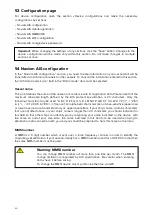
Use only one power line connection. If you connect to the NMEA2000 bus via the 

NMEA2000 Micro-C M12 5-pin connector, do not connect the power line through the universal 

power/data connector. 

Summary of Contents for AIS

Page 1: ......

Page 2: ...stallation 8 3 1 Selecting a location 8 General location requirements 8 GPS antenna location requirements 9 EMC installation guidelines 9 RF interference 10 Compass safe distance 10 3 2 Mounting the N...

Page 3: ...Alarm when a vessel is closer than 22 Notify if onboard voltage drops to 22 Closest Point of Approach CPA alarm 23 5 6 Naviom AIS NMEA0183 24 5 7 Naviom AIS Wi Fi configuration 24 5 8 Naviom AIS chang...

Page 4: ...ith the limits for a Class B digital device pursuant to Part 15 of the FCC Rules These limits are designed to provide reasonable protection against harmful interference in a residential installation T...

Page 5: ...mpliant with the essential requirements of Radio Equipment Directive 2014 53 EU AIS disclaimer All information presented by the Naviom AIS is advisory only as there is a risk of incomplete and erroneo...

Page 6: ...al accuracy disclaimer To the best of our knowledge the information in this document was correct at the time it was produced However Naviom Electronics cannot accept liability for any inaccuracies or...

Page 7: ...IS transceiver used to display real time information on local vessels land based stations or aids to navigation that are equipped with either Class A or Class B AIS transceivers 2 2 Parts supplied Des...

Page 8: ...on of all equipment Electrical interference Select a location that is far enough away from devices that may cause interference such as motors generators and radio transmitters receivers Power supply S...

Page 9: ...the effect such interference could have on the performance of your system Correct installation is required to ensure that EMC performance is not compromised For optimum EMC performance we recommend t...

Page 10: ...sure that any power cables for external equipment are not entangled with the power or data cables for GPS AIS or VHF devices Consider fitting one or more high frequency suppression ferrites to the EMI...

Page 11: ...ings approximately half way into the holes in the mounting surface 5 Fully tighten the screws Don t tighten too much it can damage the case tightness and damage the device NAVIOM AIS dimensions Import...

Page 12: ...r Note Despite the fact that NAVIOM AIS is equipped with moisture proof connectors to increase the service life of the device we recommend that when connecting the connectors to the device wear a heat...

Page 13: ...rewdriver that comes with the connector connect the cable to the connector terminals according to the diagram below For additional protection of the cable and connector against corrosion we recommend...

Page 14: ...an exposed bulkhead or deckhead use a suitable watertight feed through Do NOT run cables near to engines or fluorescent lights Always route data cables as far away as possible from Other equipment and...

Page 15: ...single length of 2 wire cable from the unit to the vessel s battery or distribution panel For power cable extensions it is recommended that a minimum wire gauge of 16 AWG 1 3 mm2 For cable runs longe...

Page 16: ...Net cable not supplied or by universal power data connector 4 6 NMEA 0183 connection The NAVIOM AIS can transmit data to devices connected via NMEA 0183 The NAVIOM AIS is connected to NMEA 0183 by uni...

Page 17: ...signal from other ships will be received and the distance at which you will be seen Use a high quality RF cable with a low attenuation the cable to the antenna should be as short as possible to reduce...

Page 18: ...device in the network environment of your computer 5 On the device webpage enter the default password NAVIOM 6 You will get an access to the device password change page and change of Wi Fi network an...

Page 19: ...nvironment Windows or Finder MacOS and open the device with the name Naviom AIS In addition you can open the device page in your Internet browser using the address http NaviomAIS local To search for a...

Page 20: ...e and are transmitted only as uppercase letters If your ship s name contains characters that are not listed above or your ship s name is longer than 20 characters you should indicate it in this field...

Page 21: ...d by your vessel through AIS channels will allow other vessels to make early decisions on maneuvering in the event of a danger of collision with you The primary goal of the AIS system is to increase s...

Page 22: ...ase of heavy maritime traffic or while in marina these notifications may be excessively frequent Notify if onboard voltage drops to This section is for informing when the supply voltage drops below a...

Page 23: ...e between the vessels at this point can be several tens of miles and there will be no need to inform about this approach Therefore in this section it is necessary to specify a dangerous distance betwe...

Page 24: ...make configuration changes view information received from other ships and operate a mobile application Be careful when making changes to this item do not forget the name and password of the Wi Fi net...

Page 25: ...ur transceiver to your MFD is set to 38 400 baud rate Ensure the MFD is either connected directly to the same CAN bus network as your AIS transceiver as the MFD that is connected to the same CAN bus a...

Page 26: ...er x 1 Receiver x 2 Operating frequency range Transmitting 156 0MHz to 162 025MHz Receiving 156 0MHz to 162 025MHz Channel spacing 25 KHz AIS performance 5 W SOTDMA GNSS receiver specification Channel...

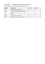
Page 27: ...ts the following NMEA 0183 sentences Sentence Description Transmit Receive ABK ABM BBM acknowledgement ACA AIS channel management assignment ACS AIS channel management information source TXT Text VDM...

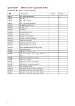
Page 28: ...OG SOG rapid update 129029 GNSS position data 129038 AIS Class A position report 129039 AIS Class B position report 129040 AIS Class B extended position report 129041 AIS AToN report 129793 AIS UTC an...

Page 29: ...d by a Class A AIS system Static data Includes information such as MMSI number vessel name vessel type call sign IMO number length beam and GNSS antenna location Voyage related data Includes informati...

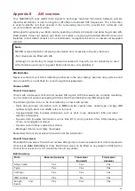
Page 30: ...or dynamic Static information is broadcast when data has been amended or upon request or by default every 6 minutes The reporting rates for dynamic information depend on speed and course change and ar...

Page 31: ...MDA 14 to 23 knots 15 Seconds SOTMDA Greater than 23 knots 5 Seconds CSTMDA 0 to 2 knots 3 Minutes CSTMDA Greater than 2 knots 30 Seconds Other AIS sources Source Reporting rate Search and Rescue SAR...

Reviews: