14 |
Installation |
Loop S User Manual
Output connector wiring
The electrical wiring, connections and installation shall be in accordance with the
requirements of ISO10133, ABYC E-11, AC and DC electrical system on boats. The wire size
should be calculated based on the channels total load and the cable length (1.31 mm2 - 5.26
mm2 (#10-16 AWG)). For bypass wires a #16 AWG cable is sufficient.
For high current loads (25-30A) connected with a long wire, thicker wires are required (e.g. 10
mm2 (#7 AWG )). In this case crimp a short 5.27 mm2 (#10 AWG) wire, maximum 20 cm (7.87”),
to the output connector pin. Then connect the thinner wire to the thicker wire with a screw
terminal block.
A proper crimping tool for barrel open terminals should be used to crimp the cables to the
wire terminals.
Always use a fuse that is appropriate for the connected load. The fuses supplied may have to
be replaced to match the outputs connected load.
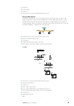
B
C
D
E
F
A
A
Wire
B
Wire seal
C
Wire terminal (female)
D
Connector body
E
Connector seal
F
Assembled connector
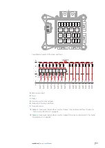
Connection examples
¼
Note:
12 V DC should be connected to the power input of the Egon+ board.
Device with bypass
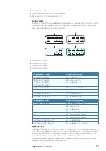
1D
1C
1B
1A
1E
1G
1H
2C
2B
2A
2E
2G
2H
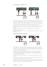
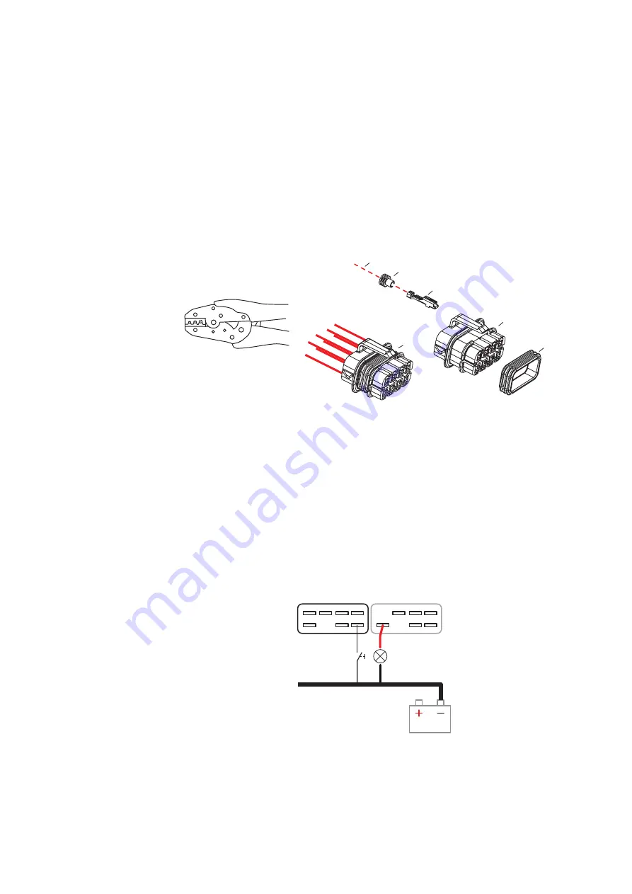
The example shows a load (light bulb) connected between the DC negative bus and the gray
connector pin 2E. Connector pin 2E is the output pin of relay R8 and can be controlled from
the Loop system.
An external bypass switch is connected to the black connector pin 1H. Connector pin 1H
is the bypass pin for relay R8. While the bypass switch is closed, the relay will be closed
independent of the status in the software. If the bypass switch is closed, it is not possible to


