background image

6 | 

Introduction | 

Loop S User Manual

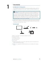
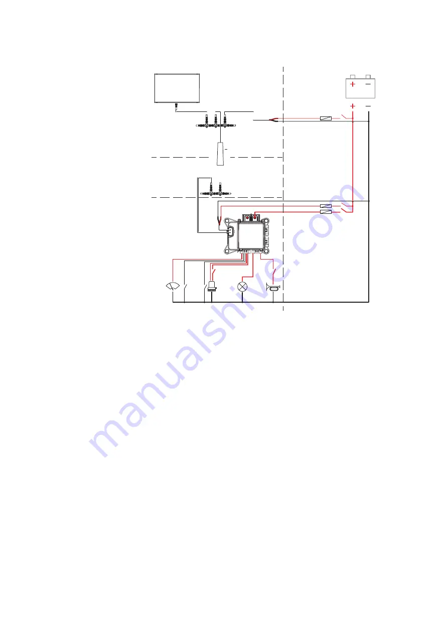
System example

NMEA 2000

Naviop CAN

Naviop 

Control system 

12 V DC

A

B

E

F

C

D

MFD

NMEA 2000 network

AT30 protocol converter

Naviop CAN network

Egon+ board

Controlled and/or monitored equipment

Get the system up and running

To get the system up and running you have to perform the following task:

• 

Installation and wiring

• 

Configuration of the system

Summary of Contents for Loop S

Page 1: ...ENGLISH LoopS User Manual www bandg com www simrad yachting com www lowrance com ...

Page 2: ......

Page 3: ...ners About this manual This manual is a reference guide for installing and operating the Loop system Some features may not be activated or available for screenshots in the manual As a result screenshots of menus and dialogs may not match the look of your unit Important text that requires special attention from the reader is emphasized as follows Note Used to draw the reader s attention to a commen...

Page 4: ... to the system 5 System parts 6 System example 6 Get the system up and running 7 Installation 7 Mounting 8 Wiring 18 Configuration 18 Requirements 18 Configuring 21 How to install the Loop S software 22 Operation 22 Start up 22 The control bar interface 24 Technical Specifications 24 Egon board 25 AT30 ...

Page 5: ...stem If the supervision system is switched off or there are communication errors between the system and the equipment it monitors all bypassed relays can be controlled manually Note For specific information on the operation of equipment that cannot be controlled by the system consult the specific technical documentation supplied by the manufacturer of the equipment not included in this manual Syst...

Page 6: ...V DC A B E F C D A MFD B NMEA 2000 network C AT30 protocol converter D Naviop CAN network E Egon board F Controlled and or monitored equipment Get the system up and running To get the system up and running you have to perform the following task Installation and wiring Configuration of the system ...
Page 7: ...ation Note The enclosure should be dry and well ventilated In small enclosures it may be required to fit forced cooling Warning Inadequate ventilation and subsequent overheating of the equipment may cause unreliable operation and reduced service life Exposing the equipment to conditions that exceeds the specifications could invalidate your warranty Refer to the Technical Specifications on page 24 ...

Page 8: ...r turned on during the installation fire electrical shock or other serious injury may occur Be sure that the voltage of the power supply is compatible with the unit Warning The electrical wiring connections and installation shall be in accordance with the requirements of ISO 10133 ABYC E 11 AC or DC electrical system on boats NMEA 2000 network A NMEA 2000 network consists of a powered backbone fro...

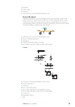
Page 9: ...irectly connected to each other The AT30 protocol converter should be installed as a bridge between the networks E C C A D B E D A AT30 protocol converter NMEA 2000 to Naviop CAN B Naviop CAN network backbone C Terminators D Drop cables maximum length 1 8 m 6 ft E Egon boards maximum 2 Egon boards can be installed Example F F A C C H B D E H I G 12 V 12 V 12 V A AT30 protocol converter NMEA 2000 t...

Page 10: ...on board is equipped with 12 V DC rated relays The input voltage should match the voltage rating of the relays Warning IGNITION PROTECTED ONLY WHEN EQUIPPED WITH IGNITION PROTECTED FUSES AND COVER CLOSED ANY REPLACEMENT FUSES MUST BE IGNITION PROTECTED COVER MUST BE CLOSED IN EVERY OPERATIONAL CONDITION Warning Always use a fuse that is appropriate for the connected load the supplied fuses may hav...

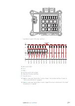
Page 11: ...F10 2C F11 2B F12 2A F15 2G F16 2H E CAN F OUT 1 OUT 2 OUT 3 OUT 4 OUT 5 OUT 6 OUT 7 OUT 8 OUT 9 OUT 10 OUT 11 OUT 12 OUT 13 OUT 14 OUT 15 OUT 16 A Main power input B Fuses C Relays D Override pins for relay outputs E Output pins for relays and fuses F Output number Note For maximum load and fuse sizes for Output 1 to 8 see Relay and fuse channels in Technical Specifications on page 24 Note For ma...

Page 12: ...able marked with the ID of the cable Egon board D 12 V DC power supply E Naviop CAN backbone F Fuse 2A Egon board power input Warning The Egon board is equipped with 12 V DC rated relays The input voltage should match the voltage rating of the relays Connect the boat s main power supply to the screw terminal M8 stud The cable must be of enough size to carry the maximum current of all loads connect...

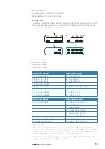
Page 13: ...bypass for relay R7 2E output relay R8 fuse F14 1G bypass for relay R6 2G output fuse F15 1H bypass for relay R8 2H output fuse F16 Output port 3 blue Output port 4 green 3A bypass for relay R4 4A output relay R1 fuse F1 4B output fuse F8 4C output fuse F6 4D output relay R4 fuse F7 4E output relay R3 fuse F5 4F output relay R2 fuse F3 3G Output relay R6 fuse F9 4G output fuse F4 3H Output relay R...

Page 14: ... used to crimp the cables to the wire terminals Always use a fuse that is appropriate for the connected load The fuses supplied may have to be replaced to match the outputs connected load B C D E F A A Wire B Wire seal C Wire terminal female D Connector body E Connector seal F Assembled connector Connection examples Note 12 V DC should be connected to the power input of the Egon board Device with ...

Page 15: ...hile the bypass switch is closed the relay will be closed independent of the status in the software If the bypass switch is closed it is not possible to turn the bilge pump supply off from the software The bypass switch is optional and only necessary if you want to be able to bypass the relay The bilge pump in this example is equipped with a float switch and the bilge pump will be running if the r...

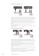
Page 16: ...onnecting an indicator light to a relay output 1D 1C 1B 1A 1E 1G 1H 2C 2B 2A 2E 2G 2H 1D 1C 1B 1A 1E 1G 1H 2C 2B 2A 2E 2G 2H The example shows a load light bulb connected between the DC negative bus and the gray connector pin 2E Connector pin 2E is the output pin of relay R8 and can be controlled from the Loop system In addition to the main load an indicator light is connected between connector pi...

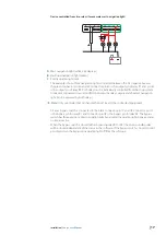
Page 17: ... connected to avoid conflicts between the relay outputs and the Mast navigation light can be powered by both relays Note Only use diodes that can handle the total load of the connected equipment A 3 way bypass switch is connected to the black connector pin 1C and 1B Connector pin 1C is the bypass pin for relay R1 and connector pin 1B is the bypass pin for relay R2 The bypass switch has three posit...

Page 18: ... configuration file created by the boat builder and or installing dealer Safe storage and retrieval of this unique file is the responsibility of the boat builder and or installing dealer It is important to make a copy of this configuration file for example on a USB stick and store in a safe location for future use Before the Loop system can be operated from the MFD it has to be configured The web ...

Page 19: ...d download a zip archive containing all files needed to install the Loop software in the boat E Set App configurator help Opens the Set App user manual F Overview of the Egon board s fuses channels with icons G Channel output settings Refer to Edit channels output settings on page 20 The settings dialog B C D A My Loop S A Loop type Define the type of the installed system S one Egon board S two Eg...

Page 20: ...ate image for the connected equipment When the icon is clicked a dialog with available options will be shown This image will be shown in the MFD software E Description Enter a name that describes the connected equipment This name will be shown in the MFD software F Enable Enable Disable the channel output G Toggle not applicable for fuse outputs If selected the button in the MFD software will be a...

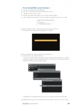
Page 21: ...D is turned off and insert the storage device in it 7 Turn the MFD on and wait until the installation is complete 8 When the MFD has booted up remove the storage device 9 Activating the Loop S control bar feature The Loop S control bar feature should be automatically enabled when the MFD is configured and the Loop system is correctly installed If it does not show up you can manually activate the f...

Page 22: ...S system is operated from the MFD s control bar Refer to the MFD documentation for details about how to operate the MFD The control bar interface Buttons The button indicates the status of the connected equipment Off black The relay is open On blue The relay is closed Override yellow The relay control is bypassed by an external switch or the equipment is powered from another source not via the rel...

Page 23: ...are replaced Note The fuses bar displays diagnostic information for fuse outputs not for fuses protecting a relay channel output The fuse outputs cannot be operated and are powered as long as the fuse is ok A Communication error If a communication error occurs all button and fuses status indicators will turn red Egon board behavior If the MFD is turned off the relays will keep their state until th...

Page 24: ...tric voltage withstanding 80 V DC Current consumption 1 5 mA battery quiescent current Total current limit 200 A Total current limit per connector 100 A Overload 135 Temperature rise 60 C Insulation resistance 10 MOhm Max load Fuse channels 30 A at 12 V DC Relay and fuse channels 20 A resistive load 16 A inductive motor pump load at 12 V DC Maximum board load 200 A Power connector 2x M8 input stud...

Page 25: ... 25 Technical Specifications Loop S User Manual AT30 Operating temperature 25 C to 65 C Power supply voltage 8 16 V DC NMEA 2000 current consumption 1 LEN CE EN 60945 ...

Page 26: ......

Page 27: ... 988 12393 002 www bandg com www simrad yachting com www lowrance com ...

Reviews: