Navistar Electrical Systems CV
Integration Guide
Page 9 of 84
Revision Date: 9/12/2019
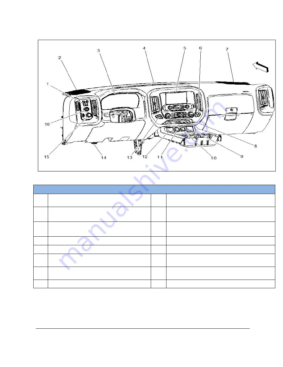
Figure 4.1.4: Instrument Panel Layout
Table 4.1.1: Instrument Panel Layout
Component Locations and Descriptions
(1)
Trailer Brake Control Switch
(9)
Accessory Power Receptacle
–
110V AC
(KI4)
(2)
Speaker
–
Left Instrument Panel (UQ3) (10) Accessory Power Receptacle
–
Instrument Panel 2
(3)
Instrument Cluster
(11) Accessory Power Receptacle
–
Instrument Panel 1
(4)
Ambient Light/Sunload Sensor
(12) USB Receptacle
(5)
Info Display Module
(13) Seat Heating and Cooling Switch
–
Driver
(6)
Seat Heating and Cooling Switch
–
Passenger
(14) Data Link Connector
(7)
Speaker
–
Right Instrument Panel
(UQ3)
(15) Headlamp Switch
(8)
Switches
–
PTO switch location
(16) Transfer Case Shift Control Switch


