background image

37

iCN 510 

| User Manual

Points of Interest (POI) Editor

You can add custom Points of Interest (POIs) using the POI Editor. A maximum of 25 Custom POIs can be saved on 
your iCN. The Custom POI fi les are listed on the 

My POI

 screen. Custom POIs can be set to announce when in close 

My POI

My POI

proximity at the 

Select Active POI

 screen.

Select Active POI

Select Active POI

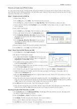
Step 1. Create a Custom POI File

1. Create a New POI File.

• On the 

Map

menu, click 

POIs

. The 

POI Editor

 window will open.

POI Editor

POI Editor

• On the 

File

menu of the POI Editor, click 

New Text File

. The 

POI File Name

 window will open.

• Type a name for the fi le in the 

File Name

 box and click 

OK

. The fi le name can be up to eight characters 

with no spaces.

2. Add a POI to the POI File.

• On the 

Edit

menu, click 

New

. The 

POI Details

 window will open.

• Type a description for the POI in the 

Description

 box.

• On the 

Degrees, Minutes, Seconds

 tab, type or select 

the degree, minute and second of the POI latitude in the 

Latitude

 boxes.

• On the 

Degrees, Minutes, Seconds

 tab, type or select 

the degree, minute and second of the POI longitude in 

the 

Longitude

 boxes.

3. Repeat step 2 until all POIs have been added to the POI fi le.
4. On the 

File

 menu, click 

Save

. The POI fi le is saved.

Step 2. Save Custom POI File to your iCN

1. On the 

File

 menu, click 

Save to Device

. The 

POI Options

 window will open.

2. Modify the POI settings as required:

• To activate the POI select the 

Active

check box. If you do 

not activate the POI, you will only be able to confi gure the 

Importance

 and 

Icon File

 settings.

• To enable a visual warning when the POI is in close proximity, 

select the 

Visual Alert

 check box.

• To enable an audible chime when the POI is in close proximity, 

select the 

Audio Alert

 check box. 

• To change the units used to measure distance for this POI, select the

Metric

 or 

Imperial

 option.

• Select the distance from the POI at which the visual warning should display or the audible chime is 

heard, from the 

Distance

 box.

• Move the 

POI Visibility Level

 slider left or right indicate the priority that the POI has where two or more 

POIs are in the same locale.

• Type the path to the icon fi le to be used to represent the POI, in the 

Icon File

 box, or select the icon fi le 

from your local or network drive clicking  , locating the fi le and clicking 

Open

. The fi le must be a bitmap 

(.BMP)  graphic with a minimum of 6x6 pixels and a maximum of 42x42 pixels.

3. Click 

OK

 and follow the prompts. The POI fi le is saved to the iCN.

OK

OK

• If you want to change the name of the fi le, edit the name for the fi le in the 

File Name

 box of the 

POI File 

Name

 window and click 

OK

. The fi le name can be up to eight characters with no spaces.

Deleting a Custom POI File from your iCN

1. On the 

Device

 menu, click

Manage POI Files

. The 

Manage POI Files

 window will open, displaying a list 

of custom POI fi les installed on your iCN.

2. Click the 

File Name

 or 

Size

 of the POI fi le to delete.

3. Click 

Delete

. The fi le is removed from the list, but is not yet deleted.

4. If you want to delete more than one fi le, go to step 2.
5. Click

OK

 and accept the c

OK

OK

hanges. The selected fi le or fi les are deleted.

Summary of Contents for iCN 510

Page 1: ...iCN 510 with Smart TM Version 3 0 User Manual Europe Australia Edition...

Page 2: ...2 iCN 510 User Manual...

Page 3: ...our Destination 13 10 Avoiding an Area 10 Avoiding an Area 10 Avoiding an Area 18 11 Viewing Your Route 19 12 Map Screen Pop up Menu 22 13 Route Demonstrator 13 Route Demonstrator 13 Route Demonstrato...

Page 4: ...gation systems The iCN GPS antenna receives GPS signals To receive GPS signals ensure the iCN is outdoors or in a vehicle outdoors and the GPS antenna has an unobstructed view of the sky The iCN can o...

Page 5: ...reset the iCN 4 Power Turns the iCN on or off When off the iCN enters a suspended state 5 Page View further screens or change map screen 6 ESC Cancels an action deletes the last text character return...

Page 6: ...3 Car Antenna Socket Connection socket for GPS car antenna not included Protected by rubber cover Side Components Component Description 1 SD MMC Slot Slot for memory card 2 Stylus Used to tap the scre...

Page 7: ...p screens Internal Battery The iCN has an internal battery that when fully charged should power the iCN for 4 hours You can monitor battery power at the Power Status screen Main Menu Settings More Set...

Page 8: ...are deleted you will need to reinstall the map to the memory card from the enclosed Map CD using Smart Desktop on your computer See Smart Desktop on your computer See Smart Desktop on page 32 Desktop...

Page 9: ...er away from the iCN The receiver will lift out to a horizontal position to allow it to obtain a GPS x 3 Use the stylus to switch the Battery Switch to ON 4 Press the Power button Power button Power T...

Page 10: ...ot use or handle the iCN when it is hot leave it to cool out of direct sunlight Suction Mount 1 Slip the locking nut over the ball foot 2 Snap the socket clip onto the ball foot and tighten the lockin...

Page 11: ...e screens You can stop the Tutorial displaying on startup by selecting the Tutorial displaying on startup by selecting the Tutorial Do not show Tutorial on startup check box 5 The Main Menu screen wil...

Page 12: ...gths screen The strength of each satellite is displayed on a bar chart The circle on the right hand side of the screen displays green when there is a valid x 2D or 3D and red when no x is available Th...

Page 13: ...the keyboard to select a town Tap the Page icon 7 To select a Road tap the textbox Use the keyboard to select a road Tap the Page icon 8 Tap the Page icon to display the Address Details screen 9 Choo...

Page 14: ...screen Go Calculates the route and displays it on the 3D Map screen To a City or Town Centre 1 From the Main Menu tap the Destination option 2 From the Destination screen tap City Town Centre The Des...

Page 15: ...to view more 9 The POI Detail screen will display Choose one of the following options POI Detail screen will display Choose one of the following options POI Detail Add to Trip Opens the Trip Planner...

Page 16: ...icon 9 Tap the Page icon to display the Address Details screen 10 Tap Add to Trip The destination point is added to your trip The Trip Planner screen will display Planner screen will display Planner...

Page 17: ...the intersection of the cross hair to a destination The street will highlight and the name will display 4 Tap the intersection of the cross hair or press the 4 way toggle button to select the street...

Page 18: ...d Area is displayed 5 Set the Avoid Area to the correct size and position using the 4 way toggle 6 Tap the Avoid Area or press the 4 way toggle button to enable the Avoid Area Deleting an Avoid Area 1...

Page 19: ...lay 2 Press the Page button to display the 3D Map screen Zoom using and on the Zoom Brightness button Use the 4 way toggle up or down to adjust the viewing angle Tap the Map screen to display the Dest...

Page 20: ...splays Distance to the next turn GPS strength indicator Tap to display the GPS Status screen Direction of the next turn Tap to hear next instruction Your current location Tap to display the Main Menu...

Page 21: ...nstruction List screen is similar to the Instruction List Next Four Turns screen except that it displays your entire route Use the Page icon to page through the instruction list Summary Tap to display...

Page 22: ...name will display 4 Tap the intersection of the cross hair or press the 4 way toggle button to display the Pop up menu 5 You can choose one of the following options Navigate To Calculates a route from...

Page 23: ...screen and place the intersection of the cross hair over a departure point using the 4 way toggle 3 Tap the intersection of the cross hair or press the 4 way toggle button to display the Pop up menu 4...

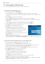
Page 24: ...l display 12 Tap the Save As box and use the left and right arrows to save as a Favourite or Shortcut 13 Tap Save to save the Favourite or Shortcut Note If you save a Shortcut over a Shortcut a warnin...

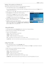
Page 25: ...rite or Edit Shortcut screen or Yes to return to the Shortcut list Using Shortcuts 1 From the Main Menu tap the Favourites option The Shortcuts screen will display 2 Select from the list The Edit Shor...

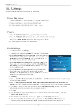
Page 26: ...eeways slider towards Use More to use freeways more often when calculating a route 5 Move the Preference for Urban Roads slider towards Use Less to use urban roads often when calculating a route Move...

Page 27: ...ce during navigation select the Enable check box 5 Tap ESC repeatedly until the Map screen displays If you have made changes to the settings tap Yes to accept the Warning dialogue box Display Settings...

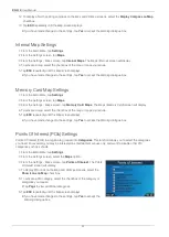
Page 28: ...display 4 To activate a map select the checkbox of the map or maps you require 5 Tap ESC repeatedly until the Map screen displays If you have made changes to the settings tap Yes to accept the Warning...

Page 29: ...t of the name of the Custom POI Press Page 5 Select the Custom POI from the list The POI Activation Settings screen will display 6 Select the Active check box to activate the POI 7 Modify the settings...

Page 30: ...dly until the Map screen displays Measurement Settings 1 From the Main Menu tap Settings 2 From the Settings screen tap More Settings 3 From the General screen tap General screen tap General Measureme...

Page 31: ...e Volume Level slider right to increase volume Move the Volume Level slider left to decrease volume Tap Test to test the volume 7 Tap ESC repeatedly until the Map screen displays If you have made chan...

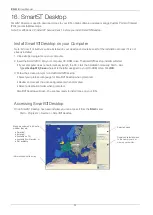
Page 32: ...Desktop installer will start Desktop installer will start If your computer does not automatically launch the CD start the installation manually Start Run Type d setup510_3 exe where d is the letter a...

Page 33: ...Smart Desktop Desktop 3 Insert a Smart Map CD into your Computer CD ROM drive the available maps will display Map CD into your Computer CD ROM drive the available maps will display 4 Click the map yo...

Page 34: ...he iCN and to your computer USB port Turn on the iCN by pressing the Power button The iCN Power button The iCN Power USB Connection screen will display when you are connected 2 Open Smart Desktop if i...

Page 35: ...iCN Power USB Connection screen will display when you are connected 2 Open Smart Desktop if it is not already open Desktop if it is not already open Start Programs Navman Smart Desktop Desktop 3 On th...

Page 36: ...s section Desktop tab Settings Colours Adjust the settings to change the look of the map type Colour Settings Description Controls map colours Displays the map border colour map colour map border widt...

Page 37: ...u do not activate the POI you will only be able to con gure the Importance and Icon File settings To enable a visual warning when the POI is in close proximity select the Visual Alert check box To ena...

Page 38: ...ccessories are available for your iCN External Antenna Required for vehicles with heated windshields and to boost GPS performance in weak signal areas Memory Card Writer Connects to your computer and...

Page 39: ...ity will be limited to the total amount actually paid by the Customer for the Software 7 The Licensor may terminate this Licence immediately if the Customer breaches any of its obligations under this...

Page 40: ...an NZ Ltd 13 17 Kawana Street Northcote Auckland New Zealand Phone 0800 GONAVMAN pcnsupport nz navman com www navman com Support for Europe Navman Europe Limited 4G Gatwick House Peeks Brook Lane Horl...

Reviews: