

1 Installation and Troubleshooting Guide
16
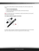
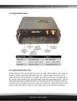
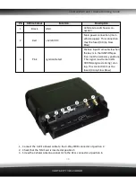
Pin
3-Wire Colour
Function
Description
1
Black
GND
Vehicle Ground/chassis con-
nection.
2
Red
+12/24V DC
Main power connection (main
vehicle supply). This connection
must be fused (3 Amp Slow
Blow).
4
Pink
Ignition Detect
Positive input from vehicle when
the key is in the IGNITION pos-
ition (not the Accessory position).
This signal must remain ON
DURING engine cranking / star-
tup. This connection must be
fused (3 Amp Slow Blow).
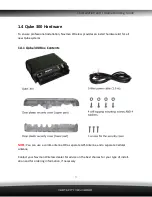
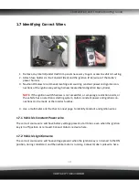
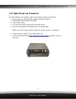
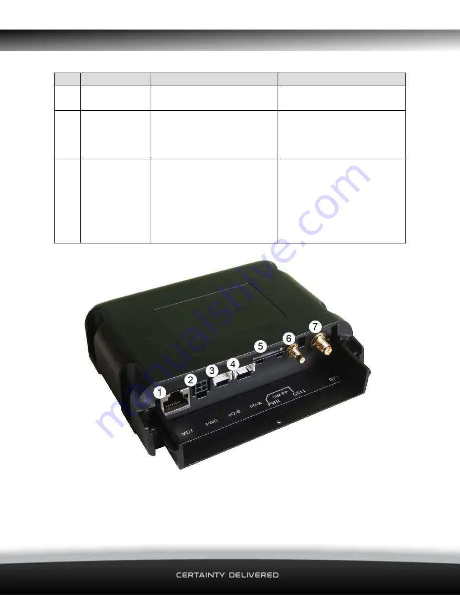
1. Connect the 3-Wire Power cable to the 4-Way PWR connector at position 2.
2. Check that the SIM Card is inserted at position 5.
3. Screw the Cellular Antenna connector to the CELL connector at position 6.
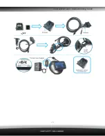
Summary of Contents for Qube 300
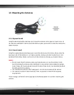
Page 10: ...1 Installation and Troubleshooting Guide 10 1 4 3 GPS Cellular Combination Antenna ...
Page 12: ...1 Installation and Troubleshooting Guide 12 ...
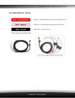
Page 13: ...1 Installation and Troubleshooting Guide 13 1 4 6 Qube 300 Power Harness ...


