Qube 2 | Installation Manual
10
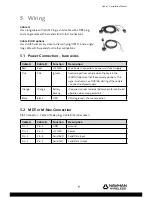
5.3 Connecting Auxiliary Devices
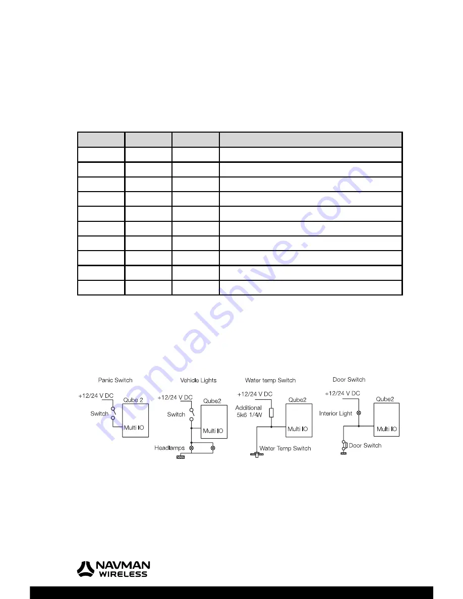
The Qube 2 is equipped with additional IO that can be connected to auxiliary devices in the
vehicle. These allow the Qube to generate events based on inputs from these devices.
Multi-IO. Each multi IO can be confi gured as digital input, analogue input or digital output.
Serial. There are two RS232 serial ports that can be confi gured as serial capture ports, MDT or
M-Nav ports etc. For serial Capture, a confi guration string is sent via the server.
Cable A
Cable B
Function
Description
Yellow
Yellow
Multi IO-1
Digital IN, analogue IN, digital OUT
Green
Green
Multi IO-2
Digital IN, analogue IN, digital OUT
Blue
Blue
Multi IO-3
Digital IN, analogue IN, digital OUT
Gray
Gray
A - GND
Analogue GND reference
White
White
+3V7 OUT
Reference voltage if required
DB9 – Pin 3
Purple
Serial TxD
Serial data OUT (Qube output)
DB9 – Pin 2
Brown
Serial RxD
Serial data IN (Qube input)
DB9 – Pin 7
Light Green
Serial RTS
Serial data fl ow control OUT
DB9 – Pin 8
Black/White
Serial CTS
Serial data fl ow control IN
DB9 – Pin 5
-
Serial GND
Serial ground
5.4 Digital
Inputs
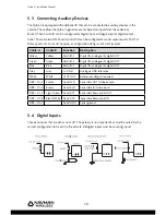
These are inputs that are either on or off. The polarity is not important but must be noted for the
correct confi guration to be sent to the vehicle. All digital inputs must be sourcing inputs.

