background image


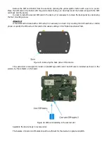
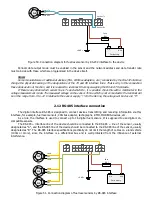
Figure 44. Appearance of Proximity-cards and keyfobs and possible variants of their readers 

 
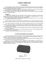
The terminal has the ability to connect temperature sensors to the 1-Wire interface using a two-wire circuit 

with “parasitic” power. Power is supplied through the same wire as the signal, therefore: the connection is made by 

two wires connected to the connector pins of the GND device (“ground”) and IBUT 1-Wire (signal and power). 


Note: 

In order to ensure better immunity with a significant length of the line connected to the 1-Wire interface, 

temperature sensors based on the DS18S20 can be connected by a three-wire circuit with a separate stabilizer supply 

voltage of 3.5 - 5V sensors. There is no such stabilizer in the device. 

In  order  the  1-Wire  interface  operates,  the  device  must  be  powered  up  with  the  main  power  supply  or 

connected by USB. When it is powered by the built-in battery, the 1-Wire interface does not work. 


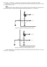
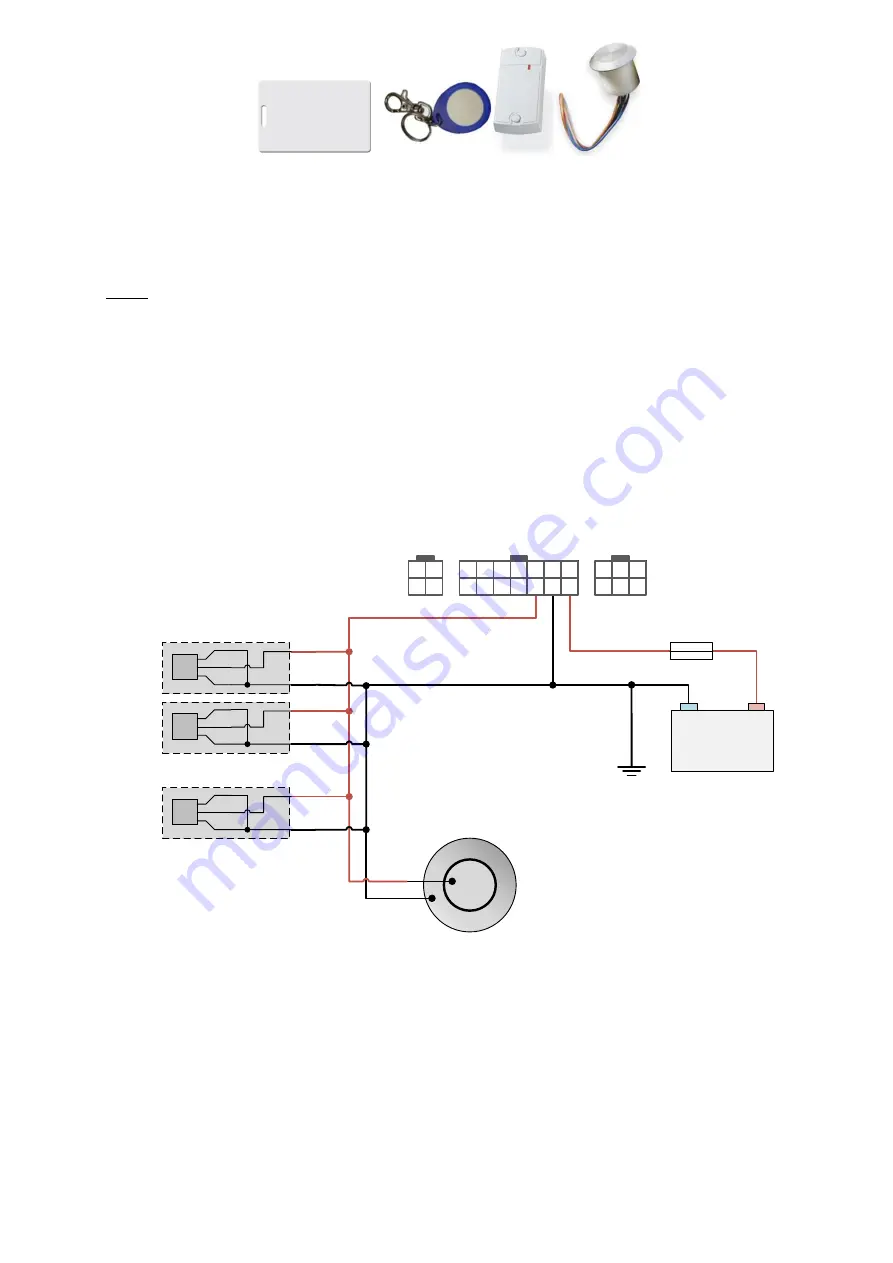
The red wire of the temperature sensor and the center pad contact TouchMemory are connected to the 1-

Wire interface (pin 3, “1-Wire”). The black wire of the temperature sensor and the side contact of the TouchMemory 

pad is connected to the negative contact of the device (pin 2, “GND”) or to the vehicle “Ground”. 

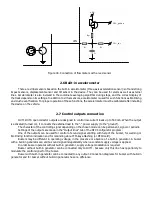
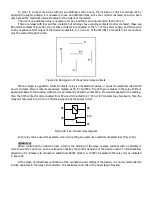
Connecting sensors and TouchMemory pads it is important to observe the topology of the common bus. This 

means that all sensors must be connected to one common two-wire cable (called as bus or trunk). It is important 

not to leave open the end of the bus that is opposite to the connected device, it should be closed by the last plug-in 

sensor. 


Fuse

(1A)

«GND»

«+»

«-»

Car battery

Temperature sensors

DS1820

Data

-

+

-

Data

+

-

Data

+

-

Data

Contact pad

Touch Memory (DS1990A)

4

2

3

1

14

7

13

6

12

5

11

4

10

3

9

8

2

1

6

5

4

3

2

1


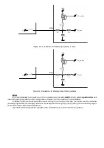
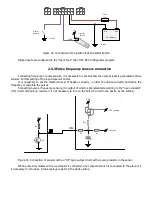
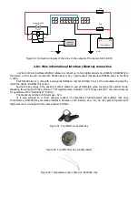
Figure 45. Connection of digital temperature sensors and TouchMemory pad 


For networks sensors construction it is necessary to choose a “twisted pair” cable, as this drastically reduces 

the effect of interference beat. It is recommended to use standard unshielded telephone wire with twisted pairs of 

category 5. This cable is available with two or four pairs of wires. During sensors network laying it is possible to use 

any cable wires. Unused wires should be left free at both ends, as their grounding increases the capacitive load. 

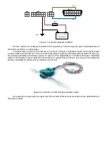
Guaranteed sensor operation is provided with a tire length of not more than 15 meters. With a further increase in 
the length of the line on the signal parameters, the electrical characteristics of the cable may be affected. If it is 

necessary to use a contact reader for DS1990 keys, it is advisable to connect it on the bus in front of temperature 

sensors, that is, closer to the device connector. 

When contacting a key to the contact pad or Proximity-cards or keyfobs to their readers connected to the 

device  in  operation  mode,  the  information  with  the key  code  and  the  time  it  was  contacted  will  be sent  to  the 

Summary of Contents for SIGNAL S-2651

Page 1: ...GPS GLONASS TRACKING EQUIPMENT SIGNAL S 2651 Operations manual Installation and connection of the device MOSCOW 2020...

Page 2: ...terested in constantly improvement of the manufactured products quality Please contact our technical support by email address support navtelecom ru should you have any questions or problems with the d...

Page 3: ...18 2 3 GSM and GLONASS GPS antennas connection 20 2 4 Power connection 20 2 5 Universal inputs connection 21 2 5 1 Analog sensors connection 21 2 5 2 Discrete sensors connection 21 2 5 3 Pulse frequen...

Page 4: ...de control of cargo safety by comprehensive measures improving driver and passenger s safety 1 3 Operational principles The device during its operation continuously monitors the status of the connecte...

Page 5: ...rate Hz 1 Power supply Operation supply voltage V2 9 5 47 High voltage pulsation protection and prolonged overvoltage up to 200V yes Current consumption at 12 V voltage in operation mode on average3...

Page 6: ...b yes Function of telemetry record to microSD card yes Telemetry records number on microSD card no less than 2 000 000 per 1 Gb Accelerometer Accelerometer with built in configured shock sensors displ...

Page 7: ...ation from three nearest towers cell towers yes Data encryption according to the AES128 standard in data transfer yes Real mileage measurement algorithm with the terrain features yes Sensors selection...

Page 8: ...r flow meters PP 01 and Avtokonduktor yes Camera connection support sending pictures to the server upon the request yes Using of information from tire pressure sensors Pressure Pro TPMS 6 13 from Park...

Page 9: ...of which Li Po battery is used cannot be used in high humidity high and low ambient temperatures Operation is permitted under the conditions specified by the manufacturer Not to hit not to deform not...

Page 10: ...on of 2 way speakerphone interface SMA connector for connecting a GSM antenna on the left SMA connector for GLONASS GPS antenna connection on the right On the side of the device unit figure 2 is locat...

Page 11: ...1 2 5 Fuse holder 1 6 14 pin connector of Microfit 14 with two power wires 1 7 6 contact connector of Microfit 6 type 1 8 4 contact connector of Microfit 4 type 1 9 Cable set of 10 installation wires...

Page 12: ...Figure 9 4 pin connector of Microfit 4 type Figure 10 Interface cable with MiniUSB connector Some cases may require connection of additional equipment not included in the standard equipment set for e...

Page 13: ...Figure 11 Fuel level sensor Figure 12 Tachograph Figure 13 External LED Figure 14 Temperature sensor...

Page 14: ...angent G 2500 Figure 16 TouchMemory contact key reader The manufacturer reserves the right to complete the devices with equipment whose set appearance and characteristics differ from those shown in th...

Page 15: ...em LED indicator 4 GLONASS GPS LED indicator 5 GSM antenna connector 6 GLONASS GPS antenna connector 7 fixing hole 8 4 pin connector 9 14 pin connector 10 6 pin connector 11 MiniUSB connector 12 SIM c...

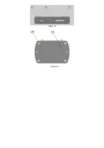
Page 16: ...Figure 19 Figure 20...

Page 17: ...1 Hz to 2000 Hz and analog voltage from 0 V to 31 V FLS impulse fuel consumption sensors DRL buttons or switches Attention It is prohibited to apply a voltage more than 50 V to the device universal i...

Page 18: ...bus adapter tachographs RFID MODBUS devices etc The digital interface RS 485 is designed for connection of various devices transmitting and receiving information on this interface for example fuel le...

Page 19: ...of the connection and settings of the device it is not recommended to directly include actuating devices in the output circuits It is advisable to do this at the final stage of verification The power...

Page 20: ...ntion If the SIM card is locked with a PIN code it is necessary to unlock it by inserting the SIM card into a mobile phone or specify the PIN code of this card in the device settings in the Data trans...

Page 21: ...removing the protective film Figure 25 GSM and GLONASS GPS antennas connection 2 4 Power connection The power supply of the system is carried out from the on board network of the car which should with...

Page 22: ...s connection The device allows to measure the voltage applied to the inputs in the range of 0 31 V When connecting analog FLS or other sensors for which the output voltage has to be monitored the volt...

Page 23: ...input through the built in pull up resistor Rpu This allows not to use an external pull up resistor when operating with sensors which operates on by ground Rpu CPU_adc R1 R2 UIN C1 CPU_pull up VDD Fi...

Page 24: ...cle ignition line and make the appropriate setting in the configuration However such connection is not mandatory In addition to the source of notifications about turning on and turning off events the...

Page 25: ...ry to set the threshold level of fixation correctly in order the device correctly determine the frequency or calculate the pulses Connecting pulse or frequency sensors the output of which is implement...

Page 26: ...n it connects the external load to the power supply to the ground The character of the controlling signal depending on the chosen mode can be permanent signal or periodic Settings of the outputs are m...

Page 27: ...motive LED lamps It is only necessary to select the LED lamp under the desired voltage of the on board vehicle network 4 2 3 1 14 7 13 6 12 5 11 4 10 3 9 8 2 1 6 5 4 3 2 1 Fuse 1 GND Car battery 1 2 k...

Page 28: ...wer contacts are always marked as 30 87 and 87a The 30th pin is always in the relay Without applying voltage to the winding contacts it is permanently closed to contact 87a If a signal is applied to t...

Page 29: ...into it at the manufacturing plant by which the device identifies this sensor Saving the key codes in the device s memory allows to use identification when changing the security mode activating the ou...

Page 30: ...t all sensors must be connected to one common two wire cable called as bus or trunk It is important not to leave open the end of the bus that is opposite to the connected device it should be closed by...

Page 31: ...connector The nominal input voltage of the audio signal at the device LOUT output is 500 mV If the amplifier has 2 channels then to increase the power you can connect both amplifier channels in paral...

Page 32: ...Such a reader allows to receive data from the CAN bus of the car without physically connecting and breaking the insulation of the wires thus avoiding problems with warranty service for new cars The d...

Page 33: ...Note There can be several CAN buses in the vehicle while information required to the user can be transmitted in different buses Since the terminal has only one CAN interface it is impossible to recei...

Page 34: ...in the range from 5 to 12 V relative to the sensor supply On the Rx line the voltage will be close to 0 2 12 RS 485 interface connection The digital interface RS 485 is designed to connect devices tra...

Page 35: ...on when the speakerphone is established with the device An electret microphone capsule is connected to pins 1 MIC and 3 MIC This microphone capsule is used in computer microphones in a compact enclos...

Page 36: ...d off There is a registration in the cellular network of the operator Weak signal 2 short flashes 1 second off There is a registration in the cellular network of the operator Medium quality signal 3 s...

Reviews: