«+»
«-»
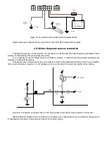
Car battery
Fuse
(1А)
«GND»
CAN L
CAN H
4
2
3
1
14
7
13
6
12
5
11
4
10
3
9
8
2
1
6
5
4
3
2
1
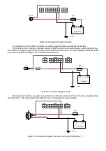
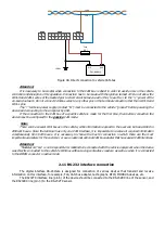
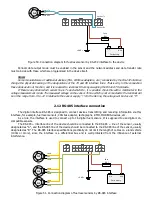
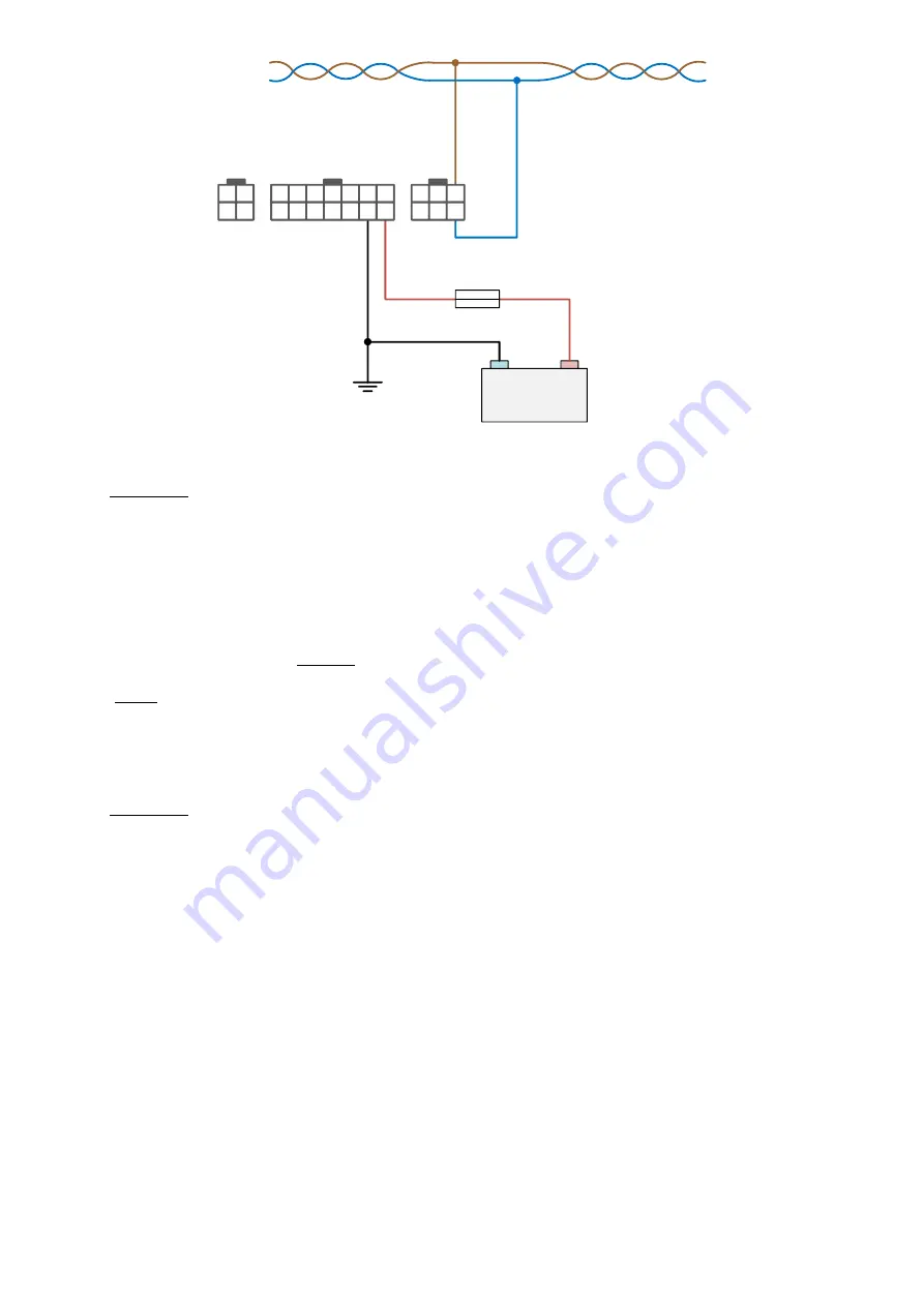
Figure 49. Direct connection to vehicle CAN-bus
Attention!
It is necessary to be careful when connection to the CAN bus is direct in order to avoid errors in the vehicle
controller and disruption of its operation. Connection has to be made with the ignition turned off. Do not allow the
CAN-H and CAN-L wires of the twisted pair to short circuit between each other, to earth, or to the “+” power of the
on-board network. Do not connect CAN bus wires to any other pins in the terminal connector other than CAN-H and
CAN-L pins.
The “-” terminal power supply (contact “G”) must be connected to the vehicle “ground” before powering the
device and connecting to the computer by USB.
If the connection to the CAN bus of a specific vehicle is made for the first time, then before connection the
device must be configured to the
passive
CAN mode.
Note:
There can be several CAN buses in the vehicle, while information required to the user can be transmitted in
different buses. Since the terminal has only one CAN interface, it is impossible to receive all required information
simultaneously from both buses. It is necessary to choose the bus for connection in which there are the most
important parameters for the customer, or use an external optional CAN bus adapter that has several CAN interfaces.
Attention!
“Navtelecom” LLC is not responsible for malfunctions connected with the vehicle equipment when the device
was directly connected to the vehicle's CAN bus without using contactless readers, as well as when it is connected
to the OBDII connector in active mode.
2.11 RS-232 interface connection
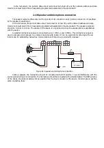
The digital interface RS-232rate is designed for connection of various devices that transmit and receive
information on this interface, for example, FLS, CAN bus adapter, tachographs, RFID, MODBUS devices, etc.
The RS232TX interface line (pin 6) of the device should be connected to the RS-232RX line of the sensor, and
the RS232RX line (pin 3) to the RS-232TX sensor.
Summary of Contents for SIGNAL S-2651
Page 16: ...Figure 19 Figure 20...

