background image


BWG-S

ERIES


O

PERATION 

& M

AINTENANCE 

M

ANUAL


12838 Stainless Drive, Holland, MI 49424 


Phone: 616/399-5600 Fax 616/399-3084 


Copyright 2018 BRAWN Mixer 

www.BRAWNMIXER.com 

Page 2 of 11


11/27/

2018 

INITIAL INSPECTION


1.  Upon receipt of your Brawn Mixer, check for possible 

shipping damage. Report any damage immediately 
to the carrier and to Brawn Mixer. 

 
2.  All Brawn Mixers are shipped with the shaft and 

impeller(s) disassembled from the drive assembly. 

 
3.  Storage:  Mixers should not be stored near vibrating 

machinery to avoid damage to the bearings. Store 
mixers as packaged by the factory. For longer 
storage periods, consult factory. If electric motors 
have been subjected to humid conditions, check the 
insulation resistance between phase and mass and 
between the different phases. The resistance should 
not be less than 100 megohms. If the resistance is 
less, please consult the factory. If mixer is stored for 
more than a year, the condition of the gear lubricant 
should be checked before the mixer is put in 
operation (see lubrication instructions). 


INSTALLATION


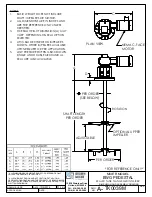
[REFER TO ASSEMBLY / DIMENSION DRAWING] 

 
Refer to the mixer installation / assembly drawing for 
important mounting structure design, assembly, 
mounting and dimensional data. 
 
1.  Install the mixer drive on the mounting structure and 

secure with properly-sized, Grade 5 or better 
hardware. Torque the hardware as recommended in 

TABLE 1


2. 

Install mixer shaft and impeller(s) (refer to shaft and 
impeller assembly section).


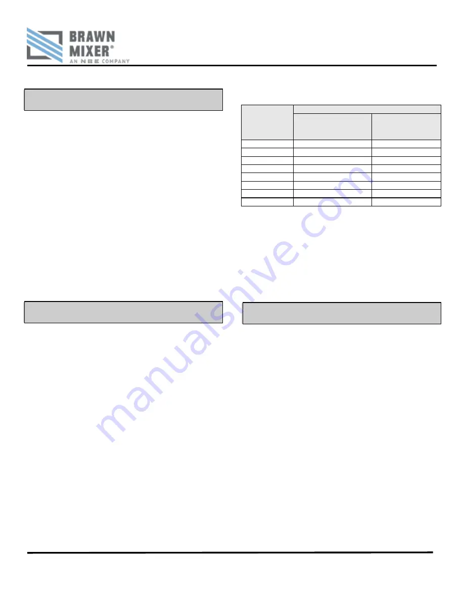
TABLE 1: RECOMMEND TORQUE VALUES 


HARDWARE 

SIZE 

TORQUE VALUES (FOOT POUNDS) 

STANDARD GRADE 2 

& 300 SERIES 

STAINLESS 

HIGH STRENGTH 

GRADES 5 & 8 

3/8-16 

17 

27 

7/16-14 

27 

40 

1/2-13 

40 

65 

9/16-12 

65 

90 

5/8-11 

85 

125 

3/4-10 

135 

225 

7/8-9 

145 

365 

1-8 

210 

545 


BOLT-TIGHTENING RECOMMENDATIONS:


Inadequately or improperly tightened hardware can 
loosen, due to vibration during mixer operation. This can 
result in reduced mixer life or damage to equipment.  
Recommended torque values for tightening all in-tank 
and mounting hardware are listed in 

TABLE 1

. These 

average torque values should be considered only as a 
guide and not as absolute values. 


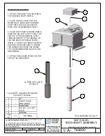
SHAFT & IMPELLER ASSEMBLY


If an optional rigid shaft coupling is furnished, connect 
the mixer shaft and rigid driveshaft couplings by carefully 
engaging the shaft rabbeted faces and installing the 
mounting hardware.  Be careful not to damage the 
coupling faces or rabbets, as this can cause excessive 
shaft run-out that will affect the life of the mixer 
 
Proper hollow output shaft installation is shown in 

FIGURE 1, PAGE 3

 
1.  Inspect the shaft surface for evidence of damage 

and repair, if required, before installing the shaft into 
hollow output shaft or connecting to flanged 
coupling. 

 
2.  Attach the shaft collar (Item 5) to the mixer shaft 

(Item 4). 

 
3.  Place the key (Item 7) on the mixer shaft and slide 

the mixer shaft into the hollow output shaft on the 
gear drive (Item 1). 


Summary of Contents for BRAWN MIXER BWG Series

Page 1: ...OPERATION AND MAINTENANCE MANUAL SERIAL NUMBER ___________________ CUSTOMER ____________________________ SALES REP ____________________________ BWG SERIES...

Page 2: ......

Page 3: ...4 SHOWN OTHER IMPELLERS AVAILABLE UPON REQUEST OR PER APPLICATION OPTIONAL PICKET FENCE IMPELLER FOR REFERENCE ONLY BSB ALL DIMENSIONS AND WEIGHTS ARE FOR REFERENCE ONLY UNLESS THE DRAWING IS CERTIFIE...

Page 4: ...ST OR PER APPLICATION LOW PRESSURE STUFFING BOX SHOWN 5 SINGLE AND DOUBLE MECHANICAL SEAL ARE ALSO AVAILABLE C NEMA C FACE MOTOR BSB ALL DIMENSIONS AND WEIGHTS ARE FOR REFERENCE ONLY UNLESS THE DRAWIN...

Page 5: ...E THE GRADE 5 HEX HEAD CAP SCREW TO THE RECOMMENDED VALUE IN THE O M MANUAL 4 ATTACH THE GUARD ITEM 2 ON THE TOP OF THE GEARDRIVE ALTERNATE CONST OF SHAFT QUANTITY VARIES DEPENDING ON SHAFT DESIGN BSB...

Page 6: ...ed while operating Develop a safety checklist for this equipment and perform regular maintenance to ensure continued and proper operation Develop a safety checklist for this equipment and perform regu...

Page 7: ...e Torque the hardware as recommended in TABLE 1 2 Install mixer shaft and impeller s refer to shaft and impeller assembly section TABLE 1 RECOMMEND TORQUE VALUES HARDWARE SIZE TORQUE VALUES FOOT POUND...

Page 8: ...red before installing the impeller s on the shaft Install the impeller s on the mixer shaft by carefully sliding the impeller hub over the shaft to its proper location and tighten the set screws It is...

Page 9: ...FOLLOWED Only qualified personnel should work on or around this equipment after becoming thoroughly familiar with all warnings safety notices and maintenance procedures contained herein The successful...

Page 10: ...dition Increase load slowly to maximum Check unit for satisfactory operation CAUTION Guard against overloading Overloading causes overheating and overheating means shortened insulation life A motor su...

Page 11: ...il companies have special bearing greases that are satisfactory Relubricate bearings every six months more often if conditions require as follows 1 Stop the motor Lock out the switch 2 Thoroughly clea...

Page 12: ...DEL PINTS 218 1 220 1 5 224 1 75 226 3 230 3 75 232 5 242 8 252 13 5 Reducers ordered from the factory will be filled to the proper level with lubricant After the installation of the breather plug the...

Page 13: ...rent phases The resistance should not be less than 100 megohms If the resistance is less please consult the factory BWG GEARBOX FEATURES SEE FIGURE ON PAGE 9 1 Rugged Cast Iron Housings provide superi...

Page 14: ...SERIES OPERATION MAINTENANCE MANUAL 12838 Stainless Drive Holland MI 49424 Phone 616 399 5600 Fax 616 399 3084 Copyright 2018 BRAWN Mixer www BRAWNMIXER com Page 9 of 11 11 27 2018 BWG GEARBOX FEATUR...

Page 15: ...Hex Head Cap Screw 10 Input Bearing 15 O Ring 16 Output Cover Gasket as required 19 Hex Head Cap Screw 26 Input Cover 27 Input Oil Seal 30 Double Input Shaft or 45 per model 40 Quill Motor Flange 41 I...

Page 16: ...hich were conducted without their prior written authorization BRAWN Mixer shall not be held liable for any further cost expense or labor to replace equipment or replaceable parts or indirect or conseq...

Page 17: ...THIS PAGE IS INTENTIONALLY LEFT BLANK...

Page 18: ...THIS PAGE IS INTENTIONALLY LEFT BLANK...

Page 19: ...THIS PAGE IS INTENTIONALLY LEFT BLANK...

Page 20: ......

Reviews: