background image

AUTOMATIC LUBRICATOR

RETAIN FOR FUTURE USE

U45250 - 3 of 3

www.nord.com/docs

01.31.17

NORD Gear Corporation

Toll Free in the United States: 888.314.6673

NORD Gear Limited

Toll Free in Canada: 800.668.4378

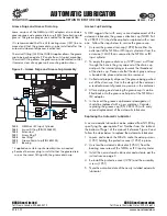
Grease Purge and Grease Drain Cup

Some versions of the NEMA (or IEC) adapters also include a 

grease purge and a grease drain cup (1299) for collecting old 

grease.  The grease purge area is sealed for transportation. 

It is recommended that the G1/4 sealing screw (1297) be re-

moved and that the grease drain cup be installed after the 

automatic lubricant dispenser is activated.

The swivel fitting (1242) that NORD supplies allows the grease 

cup to be positioned at a 90

°

 angle from its typical mounting.  

The swivel fitting allows the grease cup to be rotated so that 

it remains clear of any gear unit mounting obstructions.

Figure 3 – Grease Purge and Grease Cup Assembly

1311

1200
1243

1298
1299
1297

G1/4

1242

1200


NEMA or IEC  Input Cylinder

1242


Swivel Fitting (P/N) 22006359)

1243

 Extension*

1297


Screw Plug 

1298


Seal Ring*

1299


Grease Drain Cup (P/N 2830100)

1311

 Bearing

*  Supplied on certain input assembly sizes as needed.

  Remove the screw plug to install either the grease drain 

  cup or the swivel fitting with the grease drain cup.

Grease Cup Servicing

NORD suggests that with every second replacement of the 

automatic lubricator, the grease collection cup (NORD Part 

No. 28301210) should be emptied or replaced with a new 

one.  Follow the steps below to service the grease cup.
1.  Unscrew the grease drain cup (1299) from either the 


outlet port of the NEMA or IEC input cylinder or from the 


extension (1243) that is secured to the NEMA or IEC 


input cylinder.

2.  To empty the grease drain cup (1299) insert a stiff rod 


through the hole in the grey cap-end of the drain cup 


and push the internal plunger towards the thread-end 


of the drain cup. Please note that the dark gray end cap 


is bonded into place and cannot be removed.

3.  Collect and properly dispose of the grease being pushed 


out of the drain cup. Due to the design of the container 


a residual amount of grease may remain in the container.

4.  After emptying and cleaning the grease cup it can be 


fitted back onto the grease outlet port of the NEMA or 


IEC adaptor.

5.  In the event the grease cup becomes damaged or it 


should be replaced with a new container. Consider 


replacing the grease cup (P/N 2830100) with every 


second replacement of the automatic lubricator.

Replacing the Automatic Lubricator

A new automatic lubricator can be ordered from NORD by 

specifying the appropriate Part Number from the table at 

the bottom of Page 1 of this manual. Reference Figure 2 and 

follow the steps below to replace the automatic lubricator.
1.  Loosen and remove the M8x16 socket head cap screws 


(1251) holding the protective cover (1252) in place.

2.  Unscrew the automatic lubricator (1250-1) from the 


bearing cover area of the NEMA or IEC input cylinder.

3.  Install the new automatic lubricator and activate per the 


instructions on page 2.

4.  Re-install the protective cover (1252) and the assembly 


screws (1251).

5.  Note the activation date of the newly installed automatic 

 lubricator

Summary of Contents for BTR Series

Page 1: ...OPERATION AND MAINTENANCE MANUAL SERIAL NUMBER ___________________ CUSTOMER ____________________________ SALES REP ____________________________ BTR SERIES 150644...

Page 2: ...THIS PAGE IS INTENTIONALLY LEFT BLANK...

Page 3: ...ER J MINIMUM HARDWARE CLEARANCE REQUIRED IN MOUNTING STRUCTURE NOTES BASIC WEIGHT DOES NOT 1 INCLUDE SHAFT IMPELLERS OR MOTOR ALL DIMENSIONS ARE IN INCHES 2 2018 DATE DIMENSION AND ASSEMBLY DRAWING AP...

Page 4: ......

Page 5: ...ALUE IN THE O M MANUAL 3 ATTACH THE GUARD ITEM 2 ON THE TOP OF THE GEARDRIVE ALTERNATE SHAFT CONSTRUCTION ATTACH THE SHAFT COLLAR ITEM 7 TO THE MIXER SHAFT ITEM 4 BEFORE STEP 1 QUANTITY VARIES DEPENDI...

Page 6: ...operate this equipment unless all safety devices are installed and working properly Check all devices prior to starting the equipment Disconnect and lock out electrical power before installing or ser...

Page 7: ...fferent phases The resistance should not be less than 100 megohms If the resistance is less please consult the factory If mixer is stored for more than a year the condition of the gear lubricant shoul...

Page 8: ...lubricant level should be checked with the unit mounted in its correct operating position Lubricant should be added or removed to bring it to the correct level The catalog for the gear unit shows the...

Page 9: ...accumulated moisture Drain regularly if storage atmosphere results in formation of condensation INSTALLATION Installation must be handled by qualified service or maintenance personal OPERATION CAUTIO...

Page 10: ...necessary to ensure safe operation of the equipment Particular applications may require further procedures Dangerous voltages are present in the equipment which can cause severe personal injury and p...

Page 11: ...e motor frame or housing permits removal of accumulated moisture Drain regularly MAINTENANCE LUBRICATION Gear units should have the oil changed every 10 000 hours or 2 years If synthetic lubricant is...

Page 12: ...st a machined orifice until pressure exceeds 2 psi Above 2 psi the air is allowed to escape depressurizing the gearcase When internal pressure drops below 2 psi the autovent re seals closing the unit...

Page 13: ...ak EP2 20 to 140 Mineral Shell Cypernia RA C3 Ambient Temperature F Formulation Grease Manufacturer Grease Brand Name 58 to 230 Synthetic Texaco Starfak 2202 58 to 230 Synthetic Shell Aero Shell 5 to...

Page 14: ...ich were conducted without their prior written authorization BRAWN Mixer shall not be held liable for any further cost expense or labor to replace equipment or replaceable parts or indirect or consequ...

Page 15: ...be performed only by qualified personnel Do not operate this equipment unless all safety devices are installed and working properly Check all devices prior to starting the equipment Disconnect and loc...

Page 16: ...of lubricant that was applied during assembly it is important to completely fill the voids in the seven ring box with lubricant No further lubricant is required for the two ring box 1 Remove the lubr...

Page 17: ...inspect the shaft for damage If the shaft is significantly worn it should be repaired or replaced 5 Select the correct size and type of packing refer to the mixer specification sheet Using a bar that...

Page 18: ...engagement zone and record the measurement as B in the equation below 3 Add A B and subtract 0 08 2mm from the distance This needs to be done so that the coupling will not be preloaded after installa...

Page 19: ...IEC 132 NEMA 180TC 210TC J28 28mm 1 1 8 in 45 90 Nm 399 797 lb in IEC 100 112 NEMA 180TC M42 42 mm 1 5 8 in 100 200 Nm 885 1 770 lb in IEC 160 NEMA 250TC M48 48 mm 1 7 8 in 140 280 Nm 1240 2 478 lb i...

Page 20: ...Automatic Lubricator Principle of Operation After tightening the plastic activating screw the Zinc Molybdenum pellet drops into the Citric Acid electrolyte The chemical reaction builds up pressure tha...

Page 21: ...apped hole on the end for customer use The chart below indicated the tap size for each shaft Keys are also supplied with solid shaft Outboard pinion and sprocket fits should be as recommended by the m...

Page 22: ...ew into the motor shaft to lock coupling in place 3 Let the coupling cool down before mounting the spider into the jaws The spider should not be under axial compression when installed 4 Place the moto...

Page 23: ...esume its normal function The lubricator contains approximately 120 cm3 or 120 ml 4 8 oz of grease For reference a single stroke of a typical grease gun delivers approximately 1 0 1 2 cm3 0 03 0 04 oz...

Page 24: ...extreme highs and lows Lower ambient temperatures will lead to slower dis pensing rates and higher ambient temperatures will lead to faster dispensing rates Average Ambient Temperature Discharge Perio...

Page 25: ...ice the grease cup 1 Unscrew the grease drain cup 1299 from either the outlet port of the NEMA or IEC input cylinder or from the extension 1243 that is secured to the NEMA or IEC input cylinder 2 To e...

Page 26: ...TORQUE DRY AS SPECIFIED IN O M MANUAL BSB ALL DIMENSIONS AND WEIGHTS ARE FOR REFERENCE ONLY UNLESS THE DRAWING IS CERTIFIED ALL EQUIPMENT DESIGN AND APPLICATION DATA SHOWN HEREIN IS CONFIDENTIAL AND T...

Page 27: ...THIS PAGE IS INTENTIONALLY LEFT BLANK...

Page 28: ......

Reviews: