Installation Guide
|
Comfort Pack T Series
with up to
95% Gas Heat
13
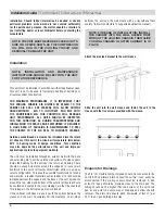
a. Line Voltage Connections
b. Connect the single phase power supply to unit fuse blower
terminal L1 and L2
c. Connect ground wire to lug
d. Low Voltage Connections
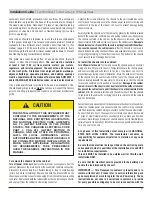
When locating the room thermostat, it should be in the natural
circulating path of room air. Avoid locations where the thermostat
would be exposed to cold air infiltration; drafts from windows,
doors or other openings leading to the outside; exposure to air
currents from warm-or-cold air registers or to exposure where the
natural circulation of the air is cut off, such as behind doors, above
or below mantels, shelves, etc.
Electrical - High Voltage
Electrical
All wiring must be installed in accordance with applicable
codes.
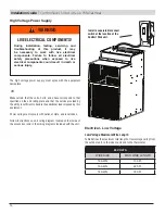
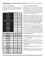
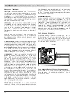
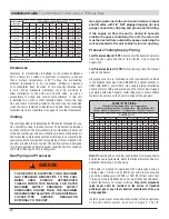
The unit is factory wired for 230/1/60 power. For 208/1/60 power
systems, the wiring to the primary side of the control transformer
should be changed from the 240-volt connection to the 208-volt
connection to provide proper operation of the control system.
The operating voltage of the unit is from 196 to 244 volts.
Operating the equipment outside of these limits will void the
warranty.
Electrical Supply and Connections
All electrical wiring and connections, including electrical grounding
must be made in accordance with the National Electric Code ANSI/
NFPA No. 70 (latest edition) or, in Canada, the Canadian Electrical
Code, Part I-C.S.A. Standard C22.1. In addition, the installer should
be aware of any local ordinances or utility company requirements
that might apply.
Check the rating plate for the supply voltage and current
requirements. A dedicated line voltage supply with fused disconnect
switch should be run directly from the main electrical panel to the
unit. All external wiring must be within approved conduit and
have a minimum temperature rise rating of 60°C. Conduit from
the disconnect switch must be run so as not to interfere with the
service panels.
Controls
Field wiring between the unit and the wall thermostat (by others)
may be low voltage for Class 2 systems. The location of the wall
thermostat should be 4 to 5 feet above the floor and carefully
selected so that the thermostat senses the temperature of the
largest conditioned area, without being influenced by drafts, sun
exposure or outside temperature.
Electrical Connections
NOTE:
Make certain that the volts, hertz, and phase correspond to
that specified on the unit rating plate, and that the service provided
by the utility is sufficient to handle the additional load imposed by
this equipment.
Make all electrical connections in accordance with the National
Electrical Code and any pertinent local codes or ordinances.
Use a separate branch electrical circuit for this unit. Locate a
disconnecting means within sight of and readily accessible to the
unit.
NOMINAL
VOLTAGE
MINIMUM
VOLTAGE
MAXIMUM
VOLTAGE
208-230
196
244
CC
C
S
R
COMP
C
H
CFM
EBM
208V
C
-
+
230V
L1
L2
CC
NEUT.
XFMER
IND
IND
Summary of Contents for Comfort Pack CP9 T Series
Page 2: ...2...


