background image

NCR


5972


2x20


Customer


Display


Release


2.0


User

ʹ

s


Guide


BD20

1372

A


Issue


F


Summary of Contents for 5972-1000

Page 1: ...NCR 5972 2x20 Customer Display Release 2 0 User s Guide BD20 1372 A Issue F...

Page 2: ...described herein may not be marketed by NCR in all parts of the world In some instances photographs are of equipment prototypes Therefore before using this document consult with your NCR representati...

Page 3: ...S curit TBTS ayant une limite de 5 amp res correspondant de fa on satisfaisante et acceptable dans le pays o le mat riel doit tre install Le source d alimentation doit tre approv e par une agence de...

Page 4: ...0 2 Chapter 1 Introduction...

Page 5: ...Site Preparation Physical Environment 2 1 Working Range 2 1 Storage Environment 2 2 Transit Environment 2 2 Dimensions 2 3 VFD Models 2 3 LCD Models 2 6 Electrical Environment 2 7 VFD AC Power Requir...

Page 6: ...tics 3 5 Micro controller Test 3 5 External Memory Test Character VFD Only 3 5 Pixel Test 3 6 Firmware Part Number Display 3 6 Chapter 4 Programming Set Up Host Retail Display Command Interface 4 1 Re...

Page 7: ...ghtness Adjustment 4 13 Read Display ID Byte 4 13 Read Display ID String 4 14 Display ESC Character 4 14 Select Character Set n 4 14 Character Sets 4 15 Code Page 850 International 4 15 Code Page Kata...

Page 8: ...Issue Date Remarks A Feb 97 First issue B Nov 98 Update to include 5972 1100 C Mar 99 Added 5963 Integrated Display Mount D Jan 03 Removed 5972 2x00 model Added dimension information E Feb 03 Added ch...

Page 9: ...o or television interference caused by unauthorized modification of this equipment or the substitution or attachment of connecting cables and equipment other than those specified by NCR The correction...

Page 10: ...0 8 Chapter 1 Introduction...

Page 11: ...Euro Symbol 5972 1300 2x20 VFD Dark Gray Low Post Mount 5972 1400 2x20 VFD Charcoal Gray Low Post Mount 5972 2400 2x20 LCD Light Gray 1m Cable 5972 2500 2x20 LCD Light Gray 4m Cable Features VFD Mode...

Page 12: ...st Charcoal Gray for 7458 Integrated Mount Telescoping Post Light Gray for 5964 Integrated Mount Telescoping Post Light Gray No Mount Software VFD control of 7x9 pixel characters Parallel I F EIA 232...

Page 13: ...in Post Table Mount Light Gray 8 in Post Table Mount Light Gray No Post Remote Mount 8 in Post Light Gray Integrated Mount Telescoping Post Light Gray for 5964 Integrated Mount Telescoping Post Light...

Page 14: ...1 4 Chapter 1 Introduction...

Page 15: ...Range Condition Range Temperature 10 C to 40 C 50 F to 104 F Temperature Change 10 C 18 F Hour Humidity Range 20 to 80 No Condensation Humidity Change 10 hour Barometric Pressure 105 000 Pa to 69000 P...

Page 16: ...s Condition Range Temperature 10 C to 50 C 14 F to 120 F Humidity 10 to 90 RH Barometric Pressure 105 000 to 70 000 Pa Transit Environment For periods up to one week Condition Range Temperature 40 to...

Page 17: ...Chapter 2 Site Preparation 2 3 Dimensions VFD Models Desktop Mount 17241 262 mm 10 3 in 162 mm 6 4 in 173 mm 6 8 in 119 mm 4 7 in 30 mm 1 2 in 178 mm 7 0 in...

Page 18: ...2 4 Chapter 2 Site Preparation 16 Inch Post 262 mm 10 3 in 15708 95 mm 3 75 in 561 mm 22 1 in 30 mm 1 2 in 119 mm 4 7 in 95 mm 3 75 in...

Page 19: ...Chapter 2 Site Preparation 2 5 8 Inch Post 20131a 95 mm 3 75 in 356 mm 14 1 in 262 mm 10 3 in 119 mm 4 7 in 356 mm 14 1 in 30 mm 1 2 in 95 mm 3 75 in...

Page 20: ...2 6 Chapter 2 Site Preparation LCD Models Desktop Mount 15412 173 mm 6 8 in 139 mm 5 5 in 30 mm 1 2 in 178 mm 7 0 in 68 mm 2 6 in 178 mm 7 0 in...

Page 21: ...LCD receives power from the host via a powered RS 232 connector LCD DC Power Requirements 10 6VDC to 13VDC 160mA max at 12VDC Operational Environment System Configuration The VFD communicates with the...

Page 22: ...2 2 P N Meters Feet Corp ID No 1416 C278 0040 1416 C278 0006 Remote Integrated Type P1 P3 P2 25 Pin D Shell Plug 8 Pin Microfit Plug 24 Pin Minifit Plug 55 mm 2 25 in Dia 32 mm 1 25 in Dia 19 mm 0 75...

Page 23: ...splay Serial Cable LCD 497 0407636 497 0407637 4 0 0 7 13 1 2 2 P N Meters Feet Corp ID No 1416 C278 0040 1416 C278 0006 Remote Integrated Type 8 Pin Microfit Plug 24 Pin Minifit Plug 9 Pin D Shell Re...

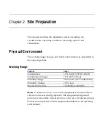
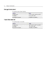
Page 24: ...2 10 Chapter 2 Site Preparation...

Page 25: ...amp res correspondant de fa on satisfaisante et acceptable dans le pays o le mat riel doit tre install Le source d alimentation doit tre approv e par une agence de normalisation appropri e et acceptab...

Page 26: ...es To qualify as reasonably trained an installer or store manager must be fluent with the terminology and basic technology of PC hardware and software This level of knowledge can typically be found in...

Page 27: ...Not all models are supported for every NCR retail terminal For specific installation instructions see the appropriate retail terminal Hardware User s Guide NCR 5952 5962 Integrated Mount 12682 2 x 20...

Page 28: ...RS 232 Serial Interface You can connect the Customer Display to one of the host terminal 9 pin serial connector Configure the terminal serial port as follows 9600 baud 8 data bits 1 start bit No pari...

Page 29: ...ions the Busy line is set active at the start of the test The first test is the Micro controller test which checks operation at the Micro controller If an error is discovered testing halts and the fir...

Page 30: ...n for two seconds The unit does not have the capability to determine if it passes this pixel test You must visually examine the display for any pixel failure Firmware Part Number Display The current f...

Page 31: ...racter 0x1B is received the subsequent byte s is processed as a command If the subsequent byte is an invalid command it is ignored If an ESC is received but no command byte is received immediately the...

Page 32: ...Default 1B 09 Set Screen Save Blank 1B 0A Set Screen Save Walk Default 1B 0B Turn On Screen Save 1B 0C Disable Screen Save Feature 1B 0D Enable Character Blink 1B 0E Disable Character Blink Default 1...

Page 33: ...External ROM required 1 1B 28 Select Character Set 9 External ROM required 1 1B 29 Select Character Set 10 External ROM required 1 1B 2A Select Character Set 11 External ROM required 1 1B 2B Select C...

Page 34: ...nes CTS for serial BUSY for parallel are placed in an exception condition see the Internal Power UP Diagnostics section in the Installation chapter The Microcontroller test consists of a check sum tes...

Page 35: ...firmware to display the current firmware part number of the device for five seconds and then step through each installed 256 character set default and user defined displaying one character at a time o...

Page 36: ...ivity the Screen Save feature could take over and cause the display to go blank or begin walking from right to left Set Low Power State On Format 1B 06 Description This state is used to reduce Retail...

Page 37: ...er character set is currently chosen For the three supported character sets the cursor is the bottom row of pixels turned on For a user defined character set the cursor is whatever is defined as chara...

Page 38: ...lay and refreshes the display in the same manner as the Set Low Power On command At power up the timer is established at five minutes and Screen Save Blank is established as a default The five minute...

Page 39: ...en Save Blank and Set Screen Save Walk commands Enable Character Blink Format 1B 0D Description The blink attribute is the only modifier which is supported for the display character positions Each tim...

Page 40: ...e cursor is enabled and blinking or not After each character is displayed the firmware performs a logical Move Cursor Right command Move Cursor Right Format 1B 10 Description Moves the cursor one posi...

Page 41: ...ed and blinking or not After each character is displayed the firmware performs a logical Move Cursor Right command Move Cursor Down Format 1B 12 Description Moves the cursor down one line When the cur...

Page 42: ...command is ignored and the cursor is moved The cursor location always indicates the position of the next character to be displayed whether the cursor is enabled and blinking or not After each characte...

Page 43: ...ult brightness setting is 5 100 Nn Brightness 01 20 02 40 03 60 04 80 05 100 Note This command is not supported by the LCD The only action taken is to take the display out of Screen Save Read Display...

Page 44: ...for the ESC character to be displayed at the current cursor position Select Character Set n Format 1B20 1B32 Description VFD only This set of commands chooses one of the three supported internal char...

Page 45: ...VFD only Code 866 Cyrillic VFD only The VFD supports 16 additional character sets of 256 characters each These additional character sets are inside a PROM that plugs into a socket on the PCB All of t...

Page 46: ...4 16 Chapter 4 Programming Set Up 014 015 016 017 018 019 020 021 022 023 024 025 026 027 028 029 030 031 032 033 034...

Page 47: ...Chapter 4 Programming Set Up 4 17 035 036 037 038 039 040 041 042 043 044 045 046 047 048 049 050 051 052 053 054 055...

Page 48: ...4 18 Chapter 4 Programming Set Up 056 057 058 059 060 061 062 063 064 065 066 067 068 069 070 071 072 073 074 075 076...

Page 49: ...Chapter 4 Programming Set Up 4 19 077 078 079 080 081 082 083 084 085 086 087 088 089 090 091 092 093 094 095 096 097...

Page 50: ...4 20 Chapter 4 Programming Set Up 098 099 100 101 102 103 104 105 106 107 108 109 110 111 112 113 114 115 116 117 118...

Page 51: ...Chapter 4 Programming Set Up 4 21 119 120 121 122 123 124 125 126 127 128 129 130 131 132 133 134 135 136 137 138 139...

Page 52: ...4 22 Chapter 4 Programming Set Up 140 141 142 143 144 145 146 147 148 149 150 151 152 153 154 155 156 157 158 159 160...

Page 53: ...Chapter 4 Programming Set Up 4 23 161 162 163 164 165 166 167 168 169 170 171 172 173 174 175 176 177 178 179 180 181...

Page 54: ...4 24 Chapter 4 Programming Set Up 182 183 184 185 186 187 188 189 190 191 192 193 194 195 196 197 198 199 200 201 202...

Page 55: ...Chapter 4 Programming Set Up 4 25 203 204 205 206 207 208 209 210 211 212 213 214 215 216 217 218 219 220 221 222 223...

Page 56: ...4 26 Chapter 4 Programming Set Up 224 225 226 227 228 229 230 231 232 233 234 235 236 237 238 239 240 241 242 243 244...

Page 57: ...Chapter 4 Programming Set Up 4 27 245 246 247 248 249 250 251 252 253 254 255...

Page 58: ...4 28 Chapter 4 Programming Set Up Code Page Katakana 000 001 002 003 004 005 006 007 008 009 010 011 012 013 014 015 016 017 018 019 020...

Page 59: ...Chapter 4 Programming Set Up 4 29 021 022 023 024 025 026 027 028 029 030 031 032 033 034 035 036 037 038 039 040 041...

Page 60: ...4 30 Chapter 4 Programming Set Up 042 043 044 045 046 047 048 049 050 051 052 053 054 055 056 057 058 059 060 061 062...

Page 61: ...Chapter 4 Programming Set Up 4 31 063 064 065 066 067 068 069 070 071 072 073 074 075 076 077 078 079 080 081 082 083...

Page 62: ...4 32 Chapter 4 Programming Set Up 084 085 086 087 088 089 090 091 092 093 094 095 096 097 098 099 100 101 102 103 104...

Page 63: ...Chapter 4 Programming Set Up 4 33 105 106 107 108 109 110 111 112 113 114 115 116 117 118 119 120 121 122 123 124 125...

Page 64: ...4 34 Chapter 4 Programming Set Up 126 127 128 129 130 131 132 133 134 135 136 137 138 139 140 141 142 143 144 145 146...

Page 65: ...Chapter 4 Programming Set Up 4 35 147 148 149 150 151 152 153 154 155 156 157 158 159 160 161 162 163 164 165 166 167...

Page 66: ...4 36 Chapter 4 Programming Set Up 168 169 170 171 172 173 174 175 176 177 178 179 180 181 182 183 184 185 186 187 188...

Page 67: ...Chapter 4 Programming Set Up 4 37 189 190 191 192 193 194 195 196 197 198 199 200 201 202 203 204 205 206 207 208 209...

Page 68: ...4 38 Chapter 4 Programming Set Up 210 211 212 213 214 215 216 217 218 219 220 221 222 223 224 225 226 227 228 229 230...

Page 69: ...Chapter 4 Programming Set Up 4 39 231 232 233 234 235 236 237 238 239 240 241 242 243 244 245 246 247 248 249 250 251...

Page 70: ...4 40 Chapter 4 Programming Set Up 252 253 254 255...

Page 71: ...Chapter 4 Programming Set Up 4 41 Code Page 866 Cyrillic 000 001 002 003 004 005 006 007 008 009 010 011 012 013 014 015 016 017 018 019 020...

Page 72: ...4 42 Chapter 4 Programming Set Up 021 022 023 024 025 026 027 028 029 030 031 032 033 034 035 036 037 038 039 040 041...

Page 73: ...Chapter 4 Programming Set Up 4 43 042 043 044 045 046 047 048 049 050 051 052 053 054 055 056 057 058 059 060 061 062...

Page 74: ...4 44 Chapter 4 Programming Set Up 063 064 065 066 067 068 069 070 071 072 073 074 075 076 077 078 079 080 081 082 083...

Page 75: ...Chapter 4 Programming Set Up 4 45 084 085 086 087 088 089 090 091 092 093 094 095 096 097 098 099 100 101 102 103 104...

Page 76: ...4 46 Chapter 4 Programming Set Up 105 106 107 108 109 110 111 112 113 114 115 116 117 118 119 120 121 122 123 124 125...

Page 77: ...Chapter 4 Programming Set Up 4 47 126 127 128 129 130 131 132 133 134 135 136 137 138 139 140 141 142 143 144 145 146...

Page 78: ...4 48 Chapter 4 Programming Set Up 147 148 149 150 151 152 153 154 155 156 157 158 159 160 161 162 163 164 165 166 167...

Page 79: ...Chapter 4 Programming Set Up 4 49 168 169 170 171 172 173 174 175 176 177 178 179 180 181 182 183 184 185 186 187 188...

Page 80: ...4 50 Chapter 4 Programming Set Up 189 190 191 192 193 194 195 196 197 198 199 200 201 202 203 204 205 206 207 208 209...

Page 81: ...Chapter 4 Programming Set Up 4 51 210 211 212 213 214 215 216 217 218 219 220 221 222 223 224 225 226 227 228 229 230...

Page 82: ...4 52 Chapter 4 Programming Set Up 231 232 233 234 235 236 237 238 239 240 241 242 243 244 245 246 247 248 249 250 251...

Page 83: ...Chapter 4 Programming Set Up 4 53 252 253 254 255...

Page 84: ...4 54 Chapter 4 Programming Set Up...

Page 85: ...o the display Caution For continued protection against risk of fire replace only with the same type and ratings of fuse The fuse is designated F1 in the Vacuum Fluorescent Display Pour pr venir et vou...

Page 86: ...be certified by the appropriate safety agency for the country of installation Le mat riel doit tre reli s electriquement au circuit Tr s Basse Tension de S curit TBTS ayant une limite de 5 amp res co...

Page 87: ...nds from the host Troubleshooting Procedures The NCR 5972 Customer Display requires minimal maintenance Should the display malfunction adhere to the procedures in the following troubleshooting chart S...

Page 88: ...ing and serial numbers indicated on the rear of the cover of the display or on the bottom of the cabinet This cover must be retained when replacing the display Do not replace this cabinet with a non s...

Page 89: ...Screws 14540 2 Remove the PC board 3 Disconnect the board from the 24 position connector 4 Reinstall a new PC board 5 Route the cable VFD Pull the cable down so the strain relief becomes flush with t...

Page 90: ...method is easiest for you Cleaning the Display Remove power from the unit before cleaning When cleaning is required a soft cloth dipped in a mild detergent can be used to clean the cabinet Only a damp...

Reviews: