background image

7156 Service Guide

Appendix B: Communication Information

September 1998

171

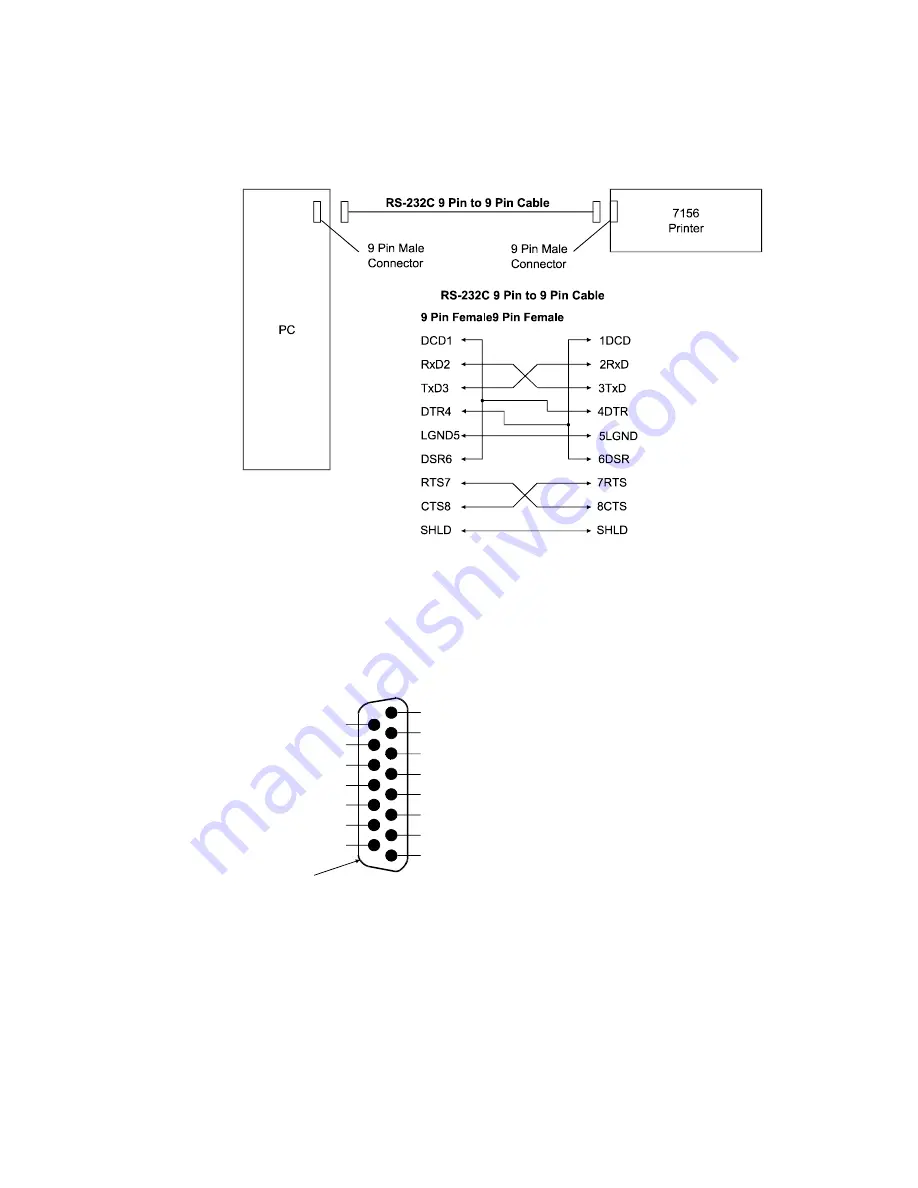
RS-232C 9-Pin to 9-Pin Cable Diagram

Note:  

This information is provided for testing and troubleshooting only.


LCSIO (RS-485) Connector and Pin Assignments

24 Volts

Power Ground

Power Ground

5 Volts

Ground

Data B

Not Used

9

10

11

12

13

14

15

Shell-Frame
Ground

1

2

3

4

5

6

7

8

24 Volts

24 Volts

Power Ground

5 Volts

Ground

 Data A 

Ground

Ground

Function

Function

Pin Numbers

Summary of Contents for 7156

Page 1: ...NCR 7156 Thermal Receipt and Impact Slip Printer Service Guide BD20 1437 A Issue B September 1997...

Page 2: ...d firmware become available No part of this document may be reproduced or transmitted in any form or by any means electronic or mechanical for any purpose without the express written permission of NCR...

Page 3: ...ication Interface Cable A shielded 360 degree interface cable must be used with this product The shield must be connected to the frame or earth ground connection or earth ground reference at EACH end...

Page 4: ...unication cables must be used with this unit to ensure compliance with the Class A FCC limits Information to User This equipment must be installed and used in strict accordance with the manufacturer s...

Page 5: ...Magnetic Ink Character Recognition MICR check reader for the common PC board and the MICR amplifier board on older LCSIO RS 485 models Running the Data Scope Mode page 35 Instructions for running the...

Page 6: ...detailed listings of what is contained in this book Who Should Use this Book You must be a trained service representative to service the 7156 Thermal Receipt and Impact printer How to Obtain More Info...

Page 7: ...g the Printer 15 Running the Print Test by Power Cycling the Printer 16 Running the Print Test by Opening and Closing the Cover 16 Sample Print Test for RS 232C Models 17 Sample Print Test for LCSIO R...

Page 8: ...PC Board Older Models 45 LCSIO RS 485 PC Board Older Models 46 Mechanical Problems 47 Printing Problems 49 Forms Feeding Problems 50 Electronic Problems 51 Chapter 5 Adjustments 53 Adjusting the Paper...

Page 9: ...eed Motor 80 Removing the Paper Feed Motor 80 Replacing the Paper Feed Motor 80 Chapter 8 Replacing the Thermal Receipt Mechanism 81 Tools 81 Replacing the Thermal Receipt Mechanism 82 Reconnecting Ca...

Page 10: ...hanism 114 Disassembling the Carriage Assembly 115 Reassembling the Carriage Assembly 116 Replacing the Carriage Assembly on the Print Mechanism 117 Chapter 13 Drive Plate Assembly 119 Tools 119 Remov...

Page 11: ...the Forms Guide Assembly 152 Disassembling the Forms Guide Assembly 153 Reassembling the Forms Guide Assembly 153 Replacing the Forms Guide Assembly in the Base 154 Chapter 18 Solenoid and Pivot Arm...

Page 12: ...Blocks 168 Appendix B Communication Information 169 RS 232C Connectors 169 RS 232C Power Cable Connector 169 Cash Drawer Connector and Pin Assignments 169 RS 232C Communication Connector Pin Assignmen...

Page 13: ...ii Appendix C Common PC Board and Extender Cables 179 Appendix D Ordering Paper and Supplies 181 Ordering Thermal Receipt Paper 181 Ordering Forms 181 Ordering Ribbon Cassettes 182 Ordering Other Supp...

Page 14: ...Contents 7156 Owner s Guide September 1998 xiv Revision Record Issue Date Remarks A September 97 First printing B September 98 Second printing including minor revisions...

Page 15: ...tting DIP Switches Connecting the Cables Turning On the Printer Testing the Printer Cleaning the Printer Chapter 3 Diagnostics Level 0 Diagnostics Level 1 Diagnostics Level 2 Diagnostics Level 3 Diagn...

Page 16: ......

Page 17: ...Green LED Note Some 7156 models may appear slightly different from what is shown in the illustration The procedures are the same for all models unless otherwise noted The 7156 printer is a fast quiet...

Page 18: ...pitch host selectable 13 9 characters per inch 66 columns Compressed pitch host selectable 17 1 characters per inch 80 columns Printing of forms up to five plies Front insertion of forms with forms s...

Page 19: ...lay Audible tone controlled by application Note The 7156 does not use a paper journal The journal is kept electronically by the host computer Options Magnetic Ink Character Recognition MICR check read...

Page 20: ...Chapter 1 About the 7156 Printer 7156 Service Guide September 1998 6...

Page 21: ...nside receipt bucket Test printout protecting the thermal printhead inside receipt bucket Cardboard support for cantilever on slip table Foam restraint for carriage behind front cover Power supply wit...

Page 22: ...the Packing Material Receipt Cover 1 2 1 Once the printer is removed from the foam pack and plastic bag open the receipt cover by pulling up on the front left corner 2 Remove the paper roll discard an...

Page 23: ...move the foam restraint and the cardboard support before using the printer Repacking the Printer Review the illustrations on the previous two pages to pack the printer 1 Place receipt paper between th...

Page 24: ...ic Ink Character Recognition MICR check reader feature has been factory adjusted for a normal operating environment with a host computer However additional devices such as CRT monitors or large metal...

Page 25: ...tic tests in Level 1 Diagnostics in Chapter 3 Diagnostics for the switch settings Caution The DIP switches are set at the factory to predetermined settings and should generally not be changed If you m...

Page 26: ...upply from its power source 2 Connect the power and communication cables to their respective connectors under the printer as shown in the illustration on the next page Be sure to screw the communicati...

Page 27: ...ing Up the Printer September 1998 13 Cable Access Cover Communication Connector Bottom of the Printer Power Cable Communication Cable Power Connector Cash Drawer Connector 1 Cash Drawer Connector 2 St...

Page 28: ...power cable through the slot at the rear of the printer 3 Connect the communication power cable to the connector in the cavity under the base at the rear 4 Connect the communication power cable to the...

Page 29: ...Troubleshooting for more information 2 Press the On Line button or plunger again to put the printer off line Note The printer receives power when the power supply is on even if the printer is off line...

Page 30: ...e 4 To stop the test press the Paper Feed button The printer is ready to receive and print data from the host computer Running the Print Test by Opening and Closing the Cover This version of the print...

Page 31: ...7156 Service Guide Chapter 2 Setting Up the Printer September 1998 17 Sample Print Test for RS 232C Models...

Page 32: ...Chapter 2 Setting Up the Printer 7156 Service Guide September 1998 18 Sample Print Test for LCSIO RS 485 Models...

Page 33: ...soap as this may damage the thermal printhead and electronics If the thermal printhead appears dirty wipe it with cotton swabs and rubbing alcohol Caution Do not use the alcohol to clean other parts o...

Page 34: ...Chapter 2 Setting Up the Printer 7156 Service Guide September 1998 20...

Page 35: ...s indicated by the printer going dead knife and printhead do not home the platen does not open LEDs are not lit the printer is unable to communicate with the host computer Knife is homed A fault condi...

Page 36: ...ged and stored in the EEROM the DIP switches must be set back to the on line settings for the printer to operate The stored settings for the functions are printed with a dump of all resident character...

Page 37: ...y 7193 Models Later 7193 Models On On On Off Off Off A A On On On Off Off On B B On On On Off On Off C C On On On Off On On D D On On On On Off Off E 3 On On On On Off On F 2 On On On On On Off G 1 On...

Page 38: ...th of Knife Cut On On Off Off Off Off 0 On On Off Off Off On 1 On On Off Off On Off 2 On On Off Off On On 3 On On Off On Off Off 4 On On Off On Off On 5 Default On On Off On On Off 6 On On Off On On O...

Page 39: ...that item 1 Open the front cover and note what the current DIP switch settings are 2 Set the DIP switches for data reception errors and the data buffer Switch 7 is always Off Switch 8 On knife Off no...

Page 40: ...non knife Switch 1 Switch 2 Switch 3 Switch 4 Switch 5 Switch 6 Option On Off On On Off On Ignore CR hexadecimal 0D On Off On On Off Off Use CR hexadecimal 0D as Print Command Default Emulates the NCR...

Page 41: ...ck and adjust the MICR check reader Check the MICR Check Reader Adjustment Caution Electro Static Discharge may damage the PC board Wear a grounded wrist strap and use a static mat or other ESD protec...

Page 42: ...of the feed rolls 8 Press the paper feed button on the PC board to take a noise sample The green LED goes off then comes back on the paper feed motor runs briefly and the MICR read head raises and dro...

Page 43: ...lowing steps several times to get the potentiometers adjusted for the least amount of noise Note The operator panel may differ depending on the model To put the printer on or off line use a paper clip...

Page 44: ...1 Reattach and close the front cover if it was removed 12 Press the On Line button or plunger on those models to put the printer on line The green LED flashes when the printer cycles The settings are...

Page 45: ...ilever d Partially close the front cover and lift off the top cover by pulling the rear wall of the top cover slightly back to release the tabs from the base 4 Replace the receipt cover a Hold the rec...

Page 46: ...roportional to the unwanted noise 6 If OK is printed on the receipt go to Replace the Covers 7 If characters are printed on the receipt perform all the steps in the next section Adjust the MICR Check...

Page 47: ...ss the paper feed button on the PC board to take a noise sample Repeat steps 4 and 5 until the lowest number of characters is printed You may need to adjust the potentiometer both directions to get th...

Page 48: ...the DIP switches to put the printer off line 3 Set the DIP switches to the settings in the table Switch 1 must be set to Off Switch 8 On knife Off non knife Switch 1 Switch 2 Switch 3 Switch 4 Switch...

Page 49: ...ct to depress the plunger in place of the On Line button on models with that item 1 Open the front cover and set the DIP switches to the following settings Switch 7 is always Off Switch 8 On knife Off...

Page 50: ...se the front cover and press the On Line button or plunger on those models The green LED flashes when the printer cycles The settings are entered into EEROM 6 Press the reset button on those models Th...

Page 51: ...check or go to step 8 to stop 8 Set the DIP switches back to the settings for normal operation on line mode See Appendix B Communication Information for the switch settings 9 Close the front cover and...

Page 52: ...re entered into EEROM 9 Press the reset button on those models The green LED flashes when the printer cycles The settings are entered into EEROM Print a Sample Receipt Single or Continuous These tests...

Page 53: ...en the following conditions occur the printer automatically turns off the appropriate motor disables printing to prevent damage and turns on the red LED flashes the red LED if the receipt printhead is...

Page 54: ...he host computer LCSIO RS 485 Models 1 Open the front cover and press the reset button under the DIP switches 2 Press and hold down the paper feed button on the top panel 3 Let go of the paper feed bu...

Page 55: ...7156 Service Guide Chapter 3 Diagnostics September 1998 41 Sample Print Test for RS 232C Models The character sets are not shown in the sample printout...

Page 56: ...Chapter 3 Diagnostics 7156 Service Guide September 1998 42 Sample Print Test for LCSIO RS 485 Models The character sets are not shown in the sample printout...

Page 57: ...ecked with a simple voltmeter The test points and their functions are listed in the following table Test Point Name Function Normal State LG Logic Ground PG Power Ground VCC 5 Volt Logic V24 24 Volt P...

Page 58: ...s compensation solenoid two FETs Q24 Q38 MICR solenoid one FET Q15 Impact printhead nine FETs Q19 Q20 Q21 Q22 Q23 Q34 Q35 Q36 Q37 Cash Drawers 1 and 2 two FETs Q18 Q32 Caution Electro Static Discharge...

Page 59: ...Q33 Slip feed motor five FETs Q20 Q21 Q22 Q23 Q24 Receipt feed motor five FETs Q36 Q37 Q38 Q39 Q40 Knife four FETs Q2 Q18 Q19 Q35 Forms compensation solenoid two FETs Q12 Q13 MICR solenoid one FET Q3...

Page 60: ...Q29 Slip feed motor five FETs Q20 Q21 Q22 Q23 Q24 Receipt feed motor five FETs Q33 Q34 Q35 Q36 Q37 Knife four FETs Q1 Q18 Q19 Q31 Forms compensation solenoid two FETs Q11 Q12 MICR solenoid one FET Q30...

Page 61: ...e Appendix B for the settings Knife motor switch not plugged in Check connections to the PC board See the section in chapter 8 that applies to this unit s PC board Failure of the knife motor or switch...

Page 62: ...s not in the proper position Check the DIP switch settings See Appendix B for the settings Improper power ground or voltage supply Make sure the power grounds are properly positioned Solenoid improper...

Page 63: ...ositioned drive plate assembly Make sure the drive plate is correctly positioned If the grommet pins are not in place the drive plate can come too far forward and bind movement in the carriage See cha...

Page 64: ...slip table and check under the carriage Remove any paper you see Problem Possible Causes What To Do Ribbon Cassette Not Functioning Jammed carriage drive Check the carriage drive for drag Ribbon caugh...

Page 65: ...paper roll see the User s Guide or RS 232C Owner s Guide for the instructions Wrong paper used Use recommended thermal receipt paper Thermal printhead is dirty Clean the thermal printhead See Cleaning...

Page 66: ...4 Problem Possible Causes What To Do Forms Skew When Feeding into Impact Printer Paper path obstruction s Remove obstruction s in the paper path Platen gap adjustment is off Check and adjust the plate...

Page 67: ...e obstructions in the paper path which may prevent inserting forms properly Both sensors have to be covered for the LED to come on One of two sensors failed Replace the sensor Failed LED Replace the L...

Page 68: ...ces such as CRT monitors or large metal surfaces that are near the printer can affect the printer s magnetic field causing intermittent reading errors when the MICR is in operation This condition can...

Page 69: ...or other adjustment procedures such as adjusting the MICR check reader and the printhead resistance see Level 1 Diagnostics in Chapter 3 Diagnostics Adjusting the Paper Low Sensor Receipt Cover Gauge...

Page 70: ...identally been changed follow these steps to re adjust it 1 Open the receipt cover 2 If the sensor is too far to either end of the cutout move it with your finger until it s closer to the center This...

Page 71: ...s long as the hinge assembly and pressure roll assembly remain attached and in the closed position You can also remove the top cover for better viewing 1 Place the wrench on the left adjusting eccentr...

Page 72: ...Chapter 5 Adjustments 7156 Service Guide September 1998 58...

Page 73: ...l disassemble and reassemble the thermal receipt mechanism In chapter 8 you will replace the thermal receipt mechanism on the printer Note Some 7156 models may appear slightly different than what is s...

Page 74: ...Chapter 6 Removing the Thermal Receipt Mechanism 7156 Service Guide September 1998 60 Removing the Receipt Cover Receipt Cover Paper Roll Silicone Fluid...

Page 75: ...se noted 1 Turn off the host computer or unplug the power supply depending on where the printer receives power 2 Disconnect the communication and power cables Models receiving power from the host comp...

Page 76: ...you will want to replace the entire receipt cover However you can replace just the platen Be careful not to damage the plastic paper guide as it is glued onto the receipt cover and is not a stock item...

Page 77: ...ewdriver to push on and release the large snap holding the top cover to the top of the cantilever 3 Remove the ESD tab on the cantilever which holds the ground wire from the tear off blade on the top...

Page 78: ...PC board MICR Read Head Cable MICR Buckhead Cable MICR Solenoid Cable See Appendix C Common PC Board and Extender Cables for more information about the extender cables See the Parts Information Manual...

Page 79: ...7156 Service Guide Chapter 6 Removing the Thermal Receipt Mechanism September 1998 65...

Page 80: ...rge may damage the PC board Wear a grounded wrist strap and use a static mat or other ESD protected work surface whenever you work with the PC board 1 Remove the following cables by gently tugging on...

Page 81: ...7156 Service Guide Chapter 6 Removing the Thermal Receipt Mechanism September 1998 67...

Page 82: ...must be used to connect the following three cables to the Common PC board MICR Read Head Cable MICR Buckhead Cable MICR Solenoid Cable See Appendix C Common PC Board for more information about the ext...

Page 83: ...7156 Service Guide Chapter 6 Removing the Thermal Receipt Mechanism September 1998 69 J12 MICR Assembly J13 Thermal Printhead Frame Ground...

Page 84: ...Thermal Mount Rear Latches 1 Open the front cover 2 Loosen the screw in front of the thermal receipt mechanism which holds it on the thermal mount Access to this screw is underneath the L bracket and...

Page 85: ...eceipt mechanism you must remove it from the printer See chapter 6 for detailed information on removing the thermal receipt mechanism In chapter 8 you will replace the thermal receipt mechanism on the...

Page 86: ...ead The knife ground strap does not need to be removed from the rotating blade 2 Remove the printhead spring by pushing or prying with a flathead screwdriver under the tab on one side Take care to pre...

Page 87: ...rsion of the printer A D are the same for all printers E H is used for early models only while 3 2 1 0 are used for later models Using the wrong printhead for the model will damage the printhead 1 Car...

Page 88: ...Receipt Mechanism 7156 Service Guide September 1998 74 Knife Assembly The knife assembly is optional and is not present in all printers Removing the Knife Assembly Set Screw Rotating Blade Left Suppo...

Page 89: ...mounting screws and the right hand support Replacing the Knife Assembly See the illustration on the previous page Note Order the knife blade kit When one part is changed all parts must be changed Be...

Page 90: ...hanism Note The knife motor needs to be removed from the print mechanism to remove the paper out switch Replacing the Knife Motor Note Order the knife motor kit if you are replacing the knife motor Th...

Page 91: ...ny of the switches The kits contain the switch screw and washer See the Parts Information Manual for more information about the kits 1 Remove the paper out switch by inserting a screwdriver in the mot...

Page 92: ...under the paper path area and insert the screwdriver through the knife motor mounting hole and replace the mounting screw washer and retaining plate 3 Replace the cover open switch under the left top...

Page 93: ...he print mechanism 2 Remove the two snap rivets by pushing the center pin through the outer jacket then pushing the outer jacket until it is flush with the sensor bracket If the rivets are damaged use...

Page 94: ...the Paper Feed Motor Caution Do not place a high speed paper feed motor in a low speed printer Likewise do not place a low speed paper feed motor in a high speed printer Low speed and high speed motor...

Page 95: ...emoving the thermal receipt mechanism and chapter 7 for detailed information on disassembling and reassembling the thermal receipt mechanism Note Some 7156 models may appear slightly different than wh...

Page 96: ...Chapter 8 Replacing the Thermal Receipt Mechanism 7156 Service Guide September 1998 82 Replacing the Thermal Receipt Mechanism Front Cover Screw Thermal Receipt Mechanism Thermal Mount Rear Latches...

Page 97: ...under Replacing the Receipt Cover 1 Position the thermal receipt mechanism on the thermal mount a Line up the latch tabs at the rear of the thermal receipt mechanism with the latches on the thermal m...

Page 98: ...ckhead Cable MICR Solenoid Cable Note In addition a longer cable for the front LED sensor is included in the kit to replace the current cable which is not long enough to connect to the new common PC b...

Page 99: ...7156 Service Guide Chapter 8 Replacing the Thermal Receipt Mechanism September 1998 85...

Page 100: ...ic Discharge may damage the PC board Wear a grounded wrist strap and use a static mat or other ESD protected work surface whenever you work with the PC board 1 Replace the following cables Receipt fee...

Page 101: ...7156 Service Guide Chapter 8 Replacing the Thermal Receipt Mechanism September 1998 87...

Page 102: ...Common PC board MICR Read Head Cable MICR Buckhead Cable MICR Solenoid Cable Note In addition a longer cable for the front LED sensor is included in the kit to replace the current cable which is not l...

Page 103: ...7156 Service Guide Chapter 8 Replacing the Thermal Receipt Mechanism September 1998 89 J12 MICR Assembly J13 Thermal Printhead Frame Ground...

Page 104: ...e front cover partially closed not latched position the top cover over the printer and PC board 2 Insert the right rear corner into the base by tilting slightly rearward 3 Swing the cover forward and...

Page 105: ...ntil the cover snaps into place 3 Close the receipt cover by pushing it down until it latches firmly into place 4 Reconnect the communication and power cables Models receiving power from the host comp...

Page 106: ...vice Guide September 1998 92 Note After reassembling the thermal receipt mechanism you may need to reset the thermal printhead resistance and the partial cut distance See Setting Printhead Resistance...

Page 107: ...nism Replacing the MICR Assembly on the Print Mechanism Chapter 12 Carriage Assembly Removing the Carriage Assembly from the Print Mechanism Disassembling the Carriage Assembly Reassembling the Carria...

Page 108: ......

Page 109: ...remove assemblies or parts from the print mechanism and then disassemble reassemble and replace the assembly or part on the print mechanism In chapter 14 you will replace the print mechanism in the p...

Page 110: ...se one cable for communication and power Remote models use one cable for communication and a separate cable for power 2 Remove the receipt cover and paper see Removing the Receipt Cover in chapter 6 3...

Page 111: ...ge may damage the PC board Wear a grounded wrist strap and use a static mat or other ESD protected work surface whenever you work with the PC board 1 Loosen the screw holding the sensor bracket to the...

Page 112: ...Chapter 9 Removing the Print Mechanism 7156 Service Guide September 1998 98 Removing the PC Board Electronics Assembly Screw PCB Shield Cantilever...

Page 113: ...ger cable for the front LED sensor is included in the kit to replace the current cable which is not long enough to connect to the new common PC board See Appendix C Common PC Board for more informatio...

Page 114: ...ber 1998 100 Removing the Thermal Mount Torx Screws Screws Print Mechanism Thermal Mount Base Ground Clip 1 Unscrew the three Torx screws on the front of the print mechanism 2 Unscrew the two screws o...

Page 115: ...extension spring connecting the hinge arm assembly to the right side of the carriage drive mechanism Caution Don t force the cover off or the arms may bend causing the cover to not work properly The...

Page 116: ...102 Removing the MICR Amplifier Board LCSIO RS 485 Models Base Print Mechanism Motor Harness Cord Keeps Amplifier Board Amplifier Board MICR Assembly LC Chip J1 Read Head Harness J2 Interconnect Conne...

Page 117: ...rd MICR Read Head Cable MICR Buckhead Cable MICR Solenoid Cable Note In addition a longer cable for the front LED sensor is included in the kit to replace the current cable which is not long enough to...

Page 118: ...assembly connections to the PC board The connections to the PC board are not marked but are keyed for reconnection 3 Remove the screw and washer connecting the print mechanism left side to the base 4...

Page 119: ...n chapter 9 Before the hinge arm assembly and the sensor bracket can be disassembled they must be removed from the print mechanism If you have not removed them see chapter 9 Tools You will need the fo...

Page 120: ...edure is upside down with the gear on the left and the pressure roll assembly toward you 1 Remove the e ring from the left side of the pressure roll assembly 2 Slide the pressure roll assembly out of...

Page 121: ...the screw Note Be sure the hinge arm is flush against the front cover 2 With the bearing on the shaft insert the right side of the pressure roll assembly into the keyed slot of the hinge arm 3 Snap th...

Page 122: ...nd off the sensor bracket 2 Pull the LED out of the light pipe 3 Remove the reflective sensor wires from between the sensor bracket posts 4 Remove the reflective sensor from the sensor bracket Reassem...

Page 123: ...rinter refer to chapter 14 Note On older LCSIO RS 485 models with the MICR amplifier board the MICR amplifier board must be removed before the print mechanism can be removed See Removing the MICR Ampl...

Page 124: ...d Head Buck Coil Assembly Buck Coil Assembly Read Head Ground Harness MICR Solenoid Solenoid Harness Service Loop Read Head Harness Buck Coil Harness Gray Wire Black Post Black Post Note Some 7156 mod...

Page 125: ...laced by peeling it off and placing on a new one See Disassembling the Carriage Assembly in chapter 12 for more information Removing the Buck Coil Assembly Note On some older models the buck coil asse...

Page 126: ...up the two studs with the holes in the cantilever 3 Replace the screw that holds the MICR bracket assembly on the front of the cantilever the read head ground wire should be under the screw 4 Thread t...

Page 127: ...embly However if you wish to remove the print mechanism first follow the procedures in chapter 9 if you haven t already done so Chapter 14 describes replacing the print mechanism in the printer Tools...

Page 128: ...er and off the right pulley gear 3 Unsnap the anti rotation bearing by pulling forward on the bottom leg and then pushing down Be careful not to break the anti rotation bearing 4 Remove the carriage d...

Page 129: ...out the carriage kit Ribbon Idler Gear Ribbon Drive Gear Step Idler Gear Flange Felt Wiper NCR 2 Anti rotation Bearing Printhead Cable Printhead Printhead Screws Silicone Fluid Ground Strap 1 Remove t...

Page 130: ...ge assembly 2 Using silicone fluid re lubricate the gear cutouts that hold the ribbon drive ribbon idler and step idler gears oil around the inside of hole and outside of hole on the step idler gear 3...

Page 131: ...eneral purpose oil or equivalent ATF oil d Slide the carriage shaft back out Be sure that the felt sleeves stay in position e Hold the carriage assembly in front of the cantilever as it will be positi...

Page 132: ...k around and thread the cable through the strain relief 5 Replace the timing belt on the drive plate assembly by pushing on the pulley gear tensioner and pulling the timing belt over and off the pulle...

Page 133: ...he drive plate assembly However if you wish to remove the print mechanism first follow the procedures in chapter 9 if you haven t already done so Chapter 14 describes replacing the print mechanism in...

Page 134: ...m the drive plate assembly by pushing against the pulley gear tensioner on the drive plate assembly while pulling the timing belt over and off the right pulley gear 2 Remove the timing belt from the o...

Page 135: ...s housing c Slide the sensor assembly off the carriage drive mounting plate 3 Remove the timing gear and home flag from the carriage drive mounting plate a Remove the e ring on top of the timing gear...

Page 136: ...earing Pulley Gear and Bearing Compression Spring Tensioner Slots Carriage Motor Assembly Motor Nut Motor Nut Motor Pinion Gear Silicone Fluid Silicone Fluid Silicone Fluid 7 Disassemble the drive ass...

Page 137: ...e the pulley flange dimple side up on top of the pulley gear c Snap the e ring to the tensioner stud above the pulley flange 5 Lubricate the home flag bearing and timing wheel bearing inside and outsi...

Page 138: ...the illustration in Removing the Drive Plate Assembly from the Print Mechanism to aid in replacing the drive plate assembly on the print mechanism Note Orientation for the following step only is with...

Page 139: ...illustrations The procedures are the same for all models unless otherwise noted Tools You will need the following tools and lubricants Torx drivers T10 and T15 018 Feeler Gauge 7 16 wrench 1 and 2 Po...

Page 140: ...e Print Mechanism 7156 Service Guide September 1998 126 Replacing the Print Mechanism Base Solenoid Wires Screw w Washer Screw w Washer Print Mechanism Read Head Harness Buck Coil Harness MICR Solenoi...

Page 141: ...ead buck coil and solenoid should exit to the right These will all plug into either of the following The MICR amplifier board on certain older LCSIO RS 485 models Extender cables that plug into the co...

Page 142: ...J3 Solenoid Connector J1 Buck Coil Connector If you are replacing the MICR amplifier board because of a failure read the following information If you are putting back the same MICR amplifier board af...

Page 143: ...ic interference will result Pull the cables taut and clip them in the base clip 2 Hold the MICR amplifier board with the blue pots on the top and reconnect the connections from the MICR assembly to th...

Page 144: ...ism Ribbon Cassette Torsion Spring 1 Position the hinges of the hinge arm assembly front cover on the brackets of the cantilever 2 Push down on the torsion springs and slide the cover forward until it...

Page 145: ...y slightly to the right of center to clear the three screw holes 4 Attach the ground clip to one of the three Torx screws used to connect the cantilever to the thermal mount and screw it through the h...

Page 146: ...4 Replacing the Print Mechanism 7156 Service Guide September 1998 132 Replacing the PC Board Motor Harness Motor Connector Cord Keeps Interconnect Harness Cord Keep Buck Coil Mount Screw Three Wires T...

Page 147: ...the extender cables See the Parts Information Manual for the kit number Caution Electro Static Discharge may damage the PC board Wear a grounded wrist strap and use a static mat or other ESD protecte...

Page 148: ...Chapter 14 Replacing the Print Mechanism 7156 Service Guide September 1998 134 Enhanced Common PC Board Connectors...

Page 149: ...7156 Service Guide Chapter 14 Replacing the Print Mechanism September 1998 135 RS 232C PC Board Connectors...

Page 150: ...Chapter 14 Replacing the Print Mechanism 7156 Service Guide September 1998 136 LCSIO RS 485 PC Board Connectors J12 MICR Assembly J13 Thermal Printhead Frame Ground...

Page 151: ...viewing as long as the hinge assembly and pressure roll assembly remain attached and in the closed position You can also remove the top cover for better viewing 1 Place the wrench on the left adjusti...

Page 152: ...ee the illustration in Removing the Sensor Bracket in chapter 9 2 Replace the slip table See the illustration in Preparation in chapter 9 3 With the hinge arm assembly front cover closed position the...

Page 153: ...Forms Compensation Arm Assembly in the Base Chapter 17 Forms Guide Assembly Removing the Forms Guide Assembly Disassembling the Forms Guide Assembly Reassembling the Forms Guide Assembly Replacing th...

Page 154: ......

Page 155: ...hat make up the base feed mechanism In chapter 20 you will replace mechanisms in the base feed mechanism to reassemble the printer Tools You will need the following tools and lubricants Torx drivers T...

Page 156: ...ble for communication and power Models receiving power from a power supply remote use one cable for communication and a separate cable for power 3 Remove the receipt cover and paper For more informati...

Page 157: ...the PC board 1 Remove the PC board For more information see Removing the PC Board in chapter 9 Make sure all connections to the PC board have been labeled for proper reconnection 2 Remove the thermal...

Page 158: ...Chapter 15 Removing the Base Feed Mechanism 7156 Service Guide September 1998 144...

Page 159: ...arated from the printer If this has not been done see chapter 15 The printer will be reassembled in chapter 20 by replacing mechanisms in the base feed mechanism Tools You will need the following tool...

Page 160: ...embly 1 Raise the forms compensation arm assembly by pulling up the pivot arm shaft to place the platen in the raised position 2 Press in on the arms of the forms compensation arm assembly and pull th...

Page 161: ...rm Shaft Bottom Feed Roll Assembly E ring Forms Compensation Arm Retaining Ring Idler Gear Platen Torx Screw Torx Screw Washer Washer Adjusting Eccentric Right Adjusting Eccentric Right Right Isolator...

Page 162: ...left isolator holders are different Reassembling the Forms Compensation Arm Assembly See the illustration on the previous page to aid in reassembling the forms compensation arm assembly Orientation f...

Page 163: ...nd forms guide assembly are not in the base feed assembly see Replacing the Forms Guide Assembly in the Base in chapter 17 and Replacing the Solenoid and Pivot Arm Assemblies in chapter 18 Orientation...

Page 164: ...Chapter 16 Forms Compensation Arm Assembly 7156 Service Guide September 1998 150...

Page 165: ...If this has not been done see chapter 15 The printer will be reassembled in chapter 20 by replacing mechanisms in the base feed mechanism Tools You will need the following tools and lubricants Torx d...

Page 166: ...removed Orientation for removing the forms guide assembly is with the forms guide assembly to the front and the paper feed motor to the right 1 Latch the solenoid in the down position 2 Free the forms...

Page 167: ...ms guide assembly Orientation for reassembling the forms guide assembly is as shown in the illustration 1 Place the slip sensor assembly in the slot on the forms guide Be sure it is oriented correctly...

Page 168: ...he illustration in Removing the Forms Guide Assembly in this chapter to aid in replacing the Forms Guide Assembly in the base 1 Hold up the pivot arm while pushing down the stop arm on the forms guide...

Page 169: ...echanism must be separated from the printer If this has not been done see chapter 15 The printer will be reassembled in chapter 20 by replacing mechanisms in the base feed mechanism Tools You will nee...

Page 170: ...Solenoid and the Pivot Arm Assembly Forms Stop Pivot Arm Pivot Arm Pivot Arm Pin Clevis Pin Clevis Pin Solenoid Pull link Solenoid Plunger Solenoid Note The solenoid and pivot arm assembly cannot be r...

Page 171: ...ot arm off the forms stop pivot arm 4 Remove the clevis pin from the solenoid pull link and pivot arm Replacing the Solenoid and the Pivot Arm Assembly Caution Keep the solenoid away from the PC board...

Page 172: ...Chapter 18 Solenoid and Pivot Arm Assemblies 7156 Service Guide September 1998 158...

Page 173: ...If this has not been done see chapter 15 The printer will be reassembled in chapter 20 by replacing mechanisms in the base feed mechanism Tools You will need the following tools and lubricants Torx dr...

Page 174: ...t the top of the motor 3 Pry the paper feed motor assembly from the base Replacing the Paper Feed Motor Assembly Orientation for this procedure is with the gear shaft on the left and the wires going t...

Page 175: ...se feed mechanism to reassemble the printer Tools You will need the following tools and lubricants Torx drivers T10 and T15 1 and 2 Pozidriv Screwdrivers Small Phillips screwdriver for 4 40 x 1875 scr...

Page 176: ...ace the wrench on the left adjusting eccentric and the feeler gauge on the left side between the platen and the printhead b Adjust the eccentric until you feel a slight drag on the gauge c Repeat step...

Page 177: ...ements Environmental Requirements Reliability Dimensions and Weight Density of Receipt Print Lines Duty Cycle Restrictions Printing Solid Blocks Appendix B Communication Information RS 232C Connectors...

Page 178: ......

Page 179: ...mum 44 Columns Standard 56 Columns Compressed 66 Columns Standard 80 Columns Compressed Print Mode Standard Compressed Double High Double Wide Upside Down Rotated Standard Compressed Double Wide Upsid...

Page 180: ...eives power either from a host computer integrated or from a separate in line power supply remote which can be purchased separately Models receiving power from the host computer use one cable for both...

Page 181: ...Temperature 5 C to 45 C 40 F to 112 F models with knife 5 C to 50 C 40 F to 120 F models with no knife Operating Humidity 5 to 90 Condensation may occur when equipment is transferred from cold to warm...

Page 182: ...enerated by the receipt thermal printhead when printing solid blocks regardless of the length of the block in relation to the print line The restrictions are ambient temperature the percentage of time...

Page 183: ...ents Pin 1 Pin 6 Pin Number Cash Drawer 1 Connector Cash Drawer 2 Connector 1 Frame Ground Frame Ground 2 Drawer 1 Solenoid Drawer 2 Solenoid Optional by jumper J13 2 to J14 2 3 Drawer 1 Status Switch...

Page 184: ...nication Information 7156 Service Guide September 1998 170 RS 232C Communication Connector Pin Assignments RS 232C 25 Pin to 9 Pin Cable Diagram Note This information is provided for testing and troub...

Page 185: ...information is provided for testing and troubleshooting only LCSIO RS 485 Connector and Pin Assignments 24 Volts Power Ground Power Ground 5 Volts Ground Data B Not Used 9 10 11 12 13 14 15 Shell Fram...

Page 186: ...ange the settings for the other functions and tests See Level 1 Diagnostics earlier in this book for more information Off Switch 1 is shown in the OFF position On DIP Switch RS 232C Switch Settings DI...

Page 187: ...ine Data Buffer Default LCSIO RS 485 Switch Settings The DIP switch on the printed circuit board is used to set the LCSIO RS 485 address bits as shown in the following illustration and table DIP Switc...

Page 188: ...legal commands are sent to the print buffer as data The commands are listed in numerical order of their hexadecimal codes according to the following categories Printer Function Commands Print Characte...

Page 189: ...B 63 33 n Select Paper End Signal Output 1B 63 34 n Select Sensors to Stop Printing 1B 63 35 n Enable or Disable Panel Switch Paper Feed Button 1B 63 36 n Enable or Disable On Line Button 1B 64 n Prin...

Page 190: ...ns 1B 3A 0 0 0 Copy Character Set From ROM to RAM 1B 47 Enable Double Strike Slip Station 1B 48 Disable Double Strike Slip Station 1B 52 n 1B 74 n Select Character Code Table 1B 56 n Set or Cancel Rot...

Page 191: ...information to the host computer and are listed in numerical order of their hexadecimal codes Printer Status Commands Hexadecimal Code Command 1B 75 0 Transmit Cash Drawer Status 1B 76 Transmit Printe...

Page 192: ...ation Not Implemented 1D 68 n Select Height of Bar Code Receipt Station 1D 6B n etc Print Bar Code Receipt Station 1D 6B 49 n Print Code 128 Bar Code Receipt Station 1D 77 n Select Horizontal Size of...

Page 193: ...e for the front LED sensor is included in the kit to replace the current cable which is not long enough to connect to the new common PC board See the Parts Information Manual for the kit number Follow...

Page 194: ...Head Connector Motor Connector Buck Coil Extender Cable Buck Coil Connector Read Head Extender Cable 3 Connect the MICR read head cable the MICR buck coil cable and the MICR Solenoid cable to the comm...

Page 195: ...printing The host computer will alert you that the paper in the receipt station is out depending on the application program running on the host computer To order thermal receipt paper contact your sa...

Page 196: ...million characters 198145 black ribbon cassette 3 million characters Ordering Other Supplies Contact your sales representative to order the supplies listed in the table The numbers are for reference o...

Page 197: ...your sales representative to order the following documentation 7156 Thermal Receipt and Impact Slip Printer Setup and User s Guide BD20 1435 A 7156 Thermal Receipt and Impact Slip Printer Service Gui...

Page 198: ...Appendix D Ordering Paper and Supplies 7156 Service Guide September 1998 184...

Page 199: ...mmunication 12 Carriage homes incorrectly 48 Carriage assembly disassembling 115 reassembling 116 removing 114 replacing 117 Carriage return ignoring using 26 Cash drawer connector pin assignments 169...

Page 200: ...5 Forms ordering 181 Forms compensation arm assembly disassembling 147 reassembling 148 removing 146 replacing 149 Forms feeding problems forms catching 51 forms not feeding 50 forms skewing 50 Forms...

Page 201: ...acing 112 MICR bracket assembly removing 111 replacing 112 MICR cables replacing with extender cables 179 MICR check reader adjusting 27 30 not operating properly 52 operating environment 10 verifying...

Page 202: ...t functioning 49 Printing continuous limitations of 168 R Receipt cover disassembling and reassembling 62 removing 60 replacing 91 Receipt mechanism disassembling 71 reassembling 71 replacing 82 Relia...

Page 203: ...3 replacing 90 Troubleshooting carriage homes incorrectly 48 FETs 44 forms catching 51 forms not feeding 50 forms skewing 50 knife does not operate 47 LED doesn t come on 51 light or spotty print ther...

Page 204: ...Index 7156 Service Guide September 1998 190...

Page 205: ......

Page 206: ...BD20 1437 A Issue B 0998 NCR is the name and mark of NCR Corporation 1997 1998 NCR Corporation Printed in U S A...

Reviews: