background image

7156 Setup and User’s Guide

Chapter 2: Setting Up and Using the Printer

September 1998

9

Choosing a Location

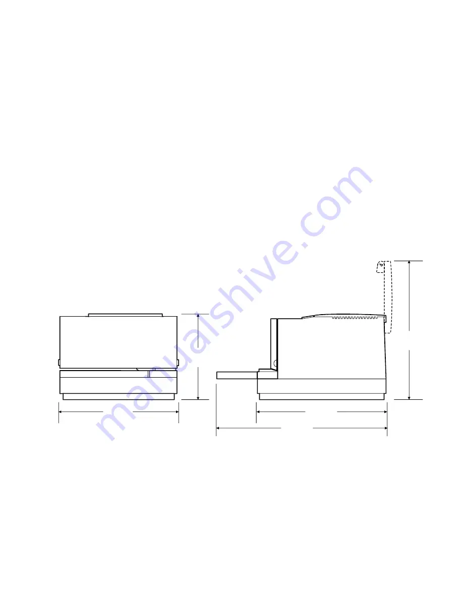
The 7156 printer takes up relatively little counter space and may be set on or near
the host computer. Make sure there is enough room to open the receipt cover to
change the paper and to open the front cover to change the ribbon cassette. The
illustration shows the actual dimensions of the printer, but leave several inches
around the printer for connecting and accessing the cables.

Note:

  The optional Magnetic Ink Character Recognition (MICR) check reader

feature has been factory adjusted for a normal operating environment with a host
computer. However, additional devices, such as CRT monitors, or large metal
surfaces that are near the printer can affect the printer’s magnetic field, causing
intermittent reading errors when the MICR check reader is in operation.

This condition can be easily diagnosed by checking the MICR check reader and
adjusting it if the factory setting has been altered by your operating environment.
See the Owner’s Guide for more information.

229 mm

(9.00 in.)

264 mm

(10.40 in.)

347 mm

(13.70 in.)

178 mm

(7.00 in.)

280 mm

(11.00 in.)

Summary of Contents for 7156

Page 1: ...NCR 7156 Thermal Receipt and Impact Slip Printer Setup and User s Guide BD20 1435 A Issue B September 1998...

Page 2: ...firmware become available No part of this document may be reproduced or transmitted in any form or by any means electronic or mechanical for any purpose without the express written permission of NCR C...

Page 3: ...ication Interface Cable A shielded 360 degree interface cable must be used with this product The shield must be connected to the frame or earth ground connection or earth ground reference at EACH end...

Page 4: ...unication cables must be used with this unit to ensure compliance with the Class A FCC limits Information to User This equipment must be installed and used in strict accordance with the manufacturer s...

Page 5: ...n 9 Connecting the Cables 10 Turning On the Printer 12 Loading and Changing the Receipt Paper 13 Removing the Paper Roll 14 Putting In the Paper Roll 15 Putting In and Changing the Ribbon Cassette 16...

Page 6: ...per and Supplies 27 Ordering Thermal Receipt Paper 27 Ordering Forms 28 Ordering Ribbon Cassettes 28 Ordering Other Supplies 29 Ordering Documentation 29 Revision Record Issue Date Remarks A September...

Page 7: ...Table Slip or Check On Line Button Paper Status Red Led On Line Green LED The 7156 printer is a fast quiet and very reliable multiple function printer Relatively small it is easy to setup and use It p...

Page 8: ...lso easy in the accommodating slip station An additional option is the Magnetic Ink Character Recognition MICR check reader with parsing which reads account numbers on checks for easy verification An...

Page 9: ...with optional extension standard with MICR check reader Snap on ribbon cassette Both Stations Variety of print modes double high receipt station only double strike slip station only double wide upside...

Page 10: ...Character Recognition MICR check reader built into the slip station for verifying checks includes custom MICR field parsing Extended slip table for handling large forms standard with MICR check reader...

Page 11: ...straint for carriage behind front cover Power supply with cable connecting to printer and power supply cord connecting to power outlet only if ordered with the printer Ribbon cassette Clips for securi...

Page 12: ...Removing the Packing Material 1 Once the printer is removed from the foam pack and plastic bag open the receipt cover by pulling up on the front left corner 2 Remove the paper roll discard any packing...

Page 13: ...emove the cardboard support from the slip table 5 Remove the ribbon cassette and cables from the box 6 Save all packing materials for future storing moving or shipping the printer 7 Complete the Insta...

Page 14: ...ge to the right and place the foam restraint between the left side of the printer and the carriage to protect the carriage 3 Place the cardboard support on the slip table 4 Place the printer in the pl...

Page 15: ...ing the cables Note The optional Magnetic Ink Character Recognition MICR check reader feature has been factory adjusted for a normal operating environment with a host computer However additional devic...

Page 16: ...under the printer as shown in the illustration Be sure to screw the communication cable to the connector on the printer 3 Route the cables through the cable clamps on the bottom of the printer then t...

Page 17: ...ng Up and Using the Printer September 1998 11 Cable Access Cover Communication Connector Bottom of the Printer Power Cable Communication Cable Power Connector Cash Drawer Connector 1 Cash Drawer Conne...

Page 18: ...he printer on line if it s not already on line The printer goes through a self test routine to ensure everything is working properly then beeps The On Line light green comes on indicating the printer...

Page 19: ...to 7 meters 5 25 feet of paper remaining on the roll Change the paper as soon as possible to avoid running out part way through a transaction Depending on the application program the host computer may...

Page 20: ...Chapter 2 Setting Up and Using the Printer 7156 Setup and User s Guide September 1998 14 Removing the Paper Roll 1 Open the receipt cover 2 Remove the used roll Receipt Cover 2 1...

Page 21: ...roll in the bin with a little extra paper extending over the front Be sure the paper unrolls from the bottom of the roll Otherwise the paper will not be printed on because the thermal coating will be...

Page 22: ...utting In and Changing the Ribbon Cassette Change the ribbon cassette when the print is too light or the ribbon is frayed Removing the Ribbon Cassette 1 Open the front cover 2 Squeeze the tabs on the...

Page 23: ...1998 17 Putting In the Ribbon Cassette 1 Tighten the ribbon by turning the knob in the direction of the arrow 2 Position the ribbon cassette on the carriage and snap it into place Be sure the ribbon...

Page 24: ...shown in the illustration from the front and place it on the slip table top first and with the print side up If the form is extra long you may need to insert it from the side 2 Slide the form or chec...

Page 25: ...7156 Setup and User s Guide Chapter 2 Setting Up and Using the Printer September 1998 19 Slip Table Extended Slip Table PAY TO THE ORDER OF DOLLARS 19 MEMO 2001 Check Orientation Guide...

Page 26: ...eck with any preset mark you may have made on the slip table The green LED on the slip table turns on when the form or check is properly inserted it has to cover two sensors on the slip table 4 Follow...

Page 27: ...Guide Chapter 2 Setting Up and Using the Printer September 1998 21 Slip Table Extended Slip Table ENDORSE HERE DO NOT WRITE STAMP OR SIGN BELOW THIS LINE RESERVED FOR FINANCIAL INSTITUTION USE Check...

Page 28: ...est 3 Let go of the Paper Feed button once the printing begins The printer prints the data and character sets until you stop it see the sample 4 To stop the test press the Paper Feed button The printe...

Page 29: ...7156 Setup and User s Guide Chapter 2 Setting Up and Using the Printer September 1998 23 Sample Print Test...

Page 30: ...ings and should generally not be changed If you must change the settings do so carefully to avoid changing other functions Before changing any of the switches first run the print test to print out the...

Page 31: ...s in level 1 diagnostics can change settings that have been pre set at the factory See the Diagnostics chapter in the Owner s Guide for more information 3 Close the cover DIP Switch Settings for RS 23...

Page 32: ...wipe it with a clean damp cloth Caution Do not spray or try to clean the thermal printhead or the inside of the printer with any kind of cleaner as this may damage the thermal printhead and the elect...

Page 33: ...inches 83 meters 273 ft 80 mm 5 mm 3 15 008 inches The paper must not be attached at the core Use paper with a colored stripe at the end to indicate that the paper is running low To order thermal rece...

Page 34: ...an 406 mm 016 inches To order forms contact your sales representative or order from NCR at the following address or toll free number NCR Media Products Division 9995 Washington Church Road Miamisburg...

Page 35: ...K320 7156 K321 7156 K322 7156 K323 7156 K324 7156 K326 RS 232C Communication cables 25 pin host to 9 pin 9 pin to 9 pin 3 meters 9 8 ft 3 meters 9 8 ft 1420 C001 0030 1416 C057 0030 Extended Slip Tabl...

Page 36: ...Chapter 3 Ordering Paper and Supplies 7156 Setup and User s Guide September 1998 30...

Page 37: ......

Page 38: ...BD20 1435 A Issue B 0998 NCR is the name and mark of NCR Corporation 1997 1998 NCR Corporation Printed in U S A...

Reviews: