6-8
Chapter 6: Communication Interface
Connector Pin-outs
This section describes the pin settings for the connectors on the back of
the printer.
Communication Connectors
The following illustrations show the RS-232C communication
connectors and pin assignments. The connectors are located at the rear
of the printer, and are specified as: male DB9, 9-pin or female DB-25, 25
pin D-shell, with RTS and CTS pins connected.
9-pin DB-9 Connector
DSR 6
RTS 7
CTS 8
Not Used 9
1 Not Used
2 RXD
3 TXD
4 DTR
5 Logic Ground
Shell-Frame Ground
Power Connector
With RS-232C, the printer is always remotely powered. The following
illustration shows the power cable connector and pin assignments. The
power cable connector is a 3-pin plug and is located at the rear of the
printer.
3 Not Used
1 Ground
Function Pin Numbers Function
+24 Volt 2
Shell - Shield
Summary of Contents for 7158
Page 1: ...NCR 7158 Thermal Receipt and Impact Printer Release 1 0 Owner s Guide B005 0000 1112 Issue D...
Page 26: ...1 8 Chapter 1 About the Printer...
Page 50: ...3 12 Chapter 3 Using the Printer Clearing Check Flip Paper Jams Check Check Flip Window Door...
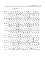
Page 110: ...5 28 Chapter 5 Technical Specifications Code Page 437...
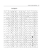
Page 111: ...Chapter 5 Technical Specifications 5 29 Code Page 850...
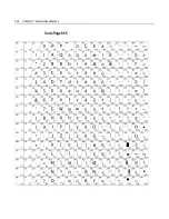
Page 112: ...5 30 Chapter 5 Technical Specifications Code Page 852...
Page 113: ...Chapter 5 Technical Specifications 5 31 Code Page 858...
Page 114: ...5 32 Chapter 5 Technical Specifications Code Page 860...
Page 115: ...Chapter 5 Technical Specifications 5 33 Code Page 863...
Page 116: ...5 34 Chapter 5 Technical Specifications Code Page 865...
Page 117: ...Chapter 5 Technical Specifications 5 35 Code Page 866...
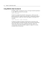
Page 128: ...6 10 Chapter 6 Communication Interface...
Page 286: ...7 158 Chapter 7 Programming Guide...
Page 314: ...Index 8 W Weight of printer 5 36 X XON XOFF protocol 6 6...


