5-4
Chapter 5: Technical Specifications
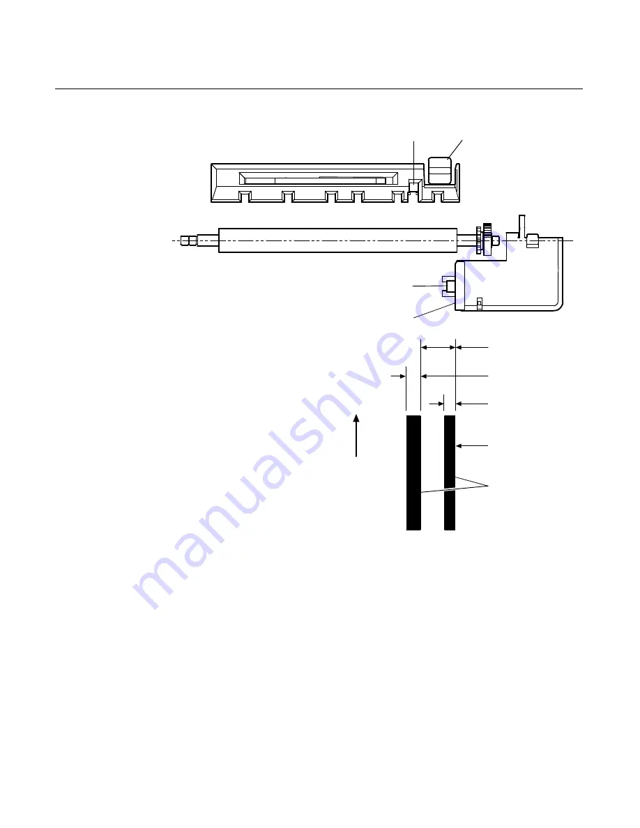
Slip Side
Guide
Paper Holes and
Low Reflection
Prohibited Areas
Slip
Edge
19 mm
(0.747 in.)
8 mm
(0.315 in.)
6 mm
(0.236 in.)
Slip/LED
Sensor
MICR
Head
Slip
Sensor
Paper Feed
Direction
B
A
The Slip/LED Sensors use a reflective photo sensor.
•
Do not use paper that has holes or is translucent at the Slip/LED
Sensor location. (See “A” in above illustration.)
•
Do not use paper that has holes on dark areas with low reflection
(less than 60% reflection) at the Slip Sensor location. (See “B” in
above illustration.)
•
Thin paper should be used between the top and bottom sheets of
multi-ply paper. Thick paper reduces the copy capability.
Summary of Contents for 7158
Page 1: ...NCR 7158 Thermal Receipt and Impact Printer Release 1 0 Owner s Guide B005 0000 1112 Issue D...
Page 26: ...1 8 Chapter 1 About the Printer...
Page 50: ...3 12 Chapter 3 Using the Printer Clearing Check Flip Paper Jams Check Check Flip Window Door...
Page 110: ...5 28 Chapter 5 Technical Specifications Code Page 437...
Page 111: ...Chapter 5 Technical Specifications 5 29 Code Page 850...
Page 112: ...5 30 Chapter 5 Technical Specifications Code Page 852...
Page 113: ...Chapter 5 Technical Specifications 5 31 Code Page 858...
Page 114: ...5 32 Chapter 5 Technical Specifications Code Page 860...
Page 115: ...Chapter 5 Technical Specifications 5 33 Code Page 863...
Page 116: ...5 34 Chapter 5 Technical Specifications Code Page 865...
Page 117: ...Chapter 5 Technical Specifications 5 35 Code Page 866...
Page 128: ...6 10 Chapter 6 Communication Interface...
Page 286: ...7 158 Chapter 7 Programming Guide...
Page 314: ...Index 8 W Weight of printer 5 36 X XON XOFF protocol 6 6...

