background image

7167 Owner’s Manual 


Chapter 3: Solving Problems 

 November 

2002 

51

MICR Check Reader Not Reading Properly 


Problem 

What to Do 

Where to Go 

MICR (Magnetic Ink Character 
Recognition) check reader does 
not read or misreads checks 

Open the slip cover and clean the MICR read 
head with cotton swabs and isopropyl  
alcohol. 

See “Adjusting the MICR 
Check Reader” in  
chapter 4. 


Summary of Contents for 7167

Page 1: ...NCR 7167 Two Station POS Printer Release 1 0 Owner s Manual B005 000 1406 Revision C November 2002...

Page 2: ...or notice All features functions and operations described herein may not be marketed by NCR in all parts of the world In some instances photographs are of equipment prototypes Therefore before using t...

Page 3: ...tion Interface Cable A shielded 360 degree interface cable must be used with this product The shield must be connected to the frame or earth ground connection or earth ground reference at EACH end of...

Page 4: ...n cables must be used with this unit to ensure compliance with the Class A FCC limits Information to User This equipment must be installed and used in strict accordance with the manufacturer s instruc...

Page 5: ...ontents or the Index Setting Up the Printer page 9 Basic requirements for unpacking and installation connecting the printer turning it on and running the print test Diagnostics page 53 Procedures for...

Page 6: ...for detailed listings of what is contained in this book Who Should Use this Book You must be a trained service representative to service the 7167 Thermal Receipt and Impact printer How to Obtain More...

Page 7: ...er Supplies 7 Ordering Documentation 7 Cleaning the Printer 8 Cleaning the Cabinet 8 Cleaning the Thermal Print Head 8 Chapter 2 Setting Up and Using the Printer 9 What Is in the Box 9 Removing the Pa...

Page 8: ...ng Fast 48 Slip or Forms Printing is Light 49 Receipt Printing is Light or Spotty 50 LED Slip Table Does Not Come On 50 Forms Skew or Catch 50 MICR Check Reader Not Reading Properly 51 Other Serious P...

Page 9: ...Bar Code Commands 83 Macro Commands 84 MICR Check Reader Commands 84 MICR Parsing 84 User Data Storage Commands 85 Asian Character Commands 85 Flash Download Commands 86 Printer Function Commands 90...

Page 10: ...5 Duty Cycle Restrictions Printing Solid Blocks 215 Appendix B Print Characteristics 217 Character Size 217 Receipt Station 217 Slip Station 218 Print Zones 221 Receipt Station 221 Slip Station 222 Sl...

Page 11: ...rface With thermal printing technology on the more frequently used receipt station there is no ribbon cassette to change and paper loading is extremely simple Printing on single or multiple part forms...

Page 12: ...per exhaust indicator Slip Station Bi directional impact printing Standard pitch host selectable 13 9 characters per inch 45 columns Compressed pitch host selectable 17 1 characters per inch 55 column...

Page 13: ...ge 1252 Windows Latin 1 PC Code Page Katakana Space Page Code Page 932 Code Page 936 Code Page 949 Code Page 950 16K RAM for downloaded character sets or bit mapped graphics such as logos General Feat...

Page 14: ...information Note The thermal print head does not normally require cleaning if the recommended paper is used If non recommended paper has been used for an extended period of time cleaning the print hea...

Page 15: ...k Paper Grade Description 856911 Economy for text printing 856966 Standard Sensitivity for text and simple graphics 878559 High Sensitivity for text bar codes detailed graphics 856380 For improved arc...

Page 16: ...the cardstock must be the last ply of the form To order forms contact your sales representative or order from NCR at the following address or toll free number NCR Media Products Division 9995 Washingt...

Page 17: ...us Power Cable DC Power from NCR POS Terminal DC Power from NCR POS Terminal 1 0 Meters 4 0 Meters 1416 C712 0010 1416 C712 0040 USB Communication Cables USB Type A to Type B Connector USB Type A to T...

Page 18: ...rint Head Caution Do not spray or try to clean the thermal print head or the inside of the printer with any kind of cleaner as this may damage the thermal print head and electronics If the thermal pri...

Page 19: ...plastic bag and foam pack Ribbon cassette Thermal receipt paper roll Cardboard restraint for carriage behind front cover These items may be ordered as options from NCR and will be shipped separately...

Page 20: ...inter November 2002 10 Removing the Packing Material 1 Remove the printer from the foam pack and plastic bag 2 Open the front cover and remove the carriage holder 3 Remove the head gap holder from the...

Page 21: ...5 If you are sending the printer to NCR for repair call your NCR authorized service representative for instructions on where to send the printer Be prepared to answer questions concerning shipping an...

Page 22: ...y may be mounted on a vertical wall by using the holes on the cover Mount the screws on the wall using the following recommended mount dimensions Use a 8 wood screw which is to be securely fastened to...

Page 23: ...gnostic tests in Level 1 Diagnostics in Chapter 4 Diagnostics for Setting Up The Printer Caution The DIP switches are set to OFF Note Switch 1 is shown in the Off position for reference Use a paper cl...

Page 24: ...ys connect the communication cable and cash drawer cables before connecting power to the power source Always disconnect power to the power source before disconnecting the communication and cash drawer...

Page 25: ...is point the printer receives power If the On Line LED green is on the printer is on line Otherwise the printer is not receiving power Check to insure that the host terminal is on or that the power su...

Page 26: ...7167 Owner s Manual Chapter 2 Setting Up and Using the Printer November 2002 16 Bottom of the Printer...

Page 27: ...e POS industry for a couple of reasons Additional POS devices Some POS systems are required to host more peripherals than can be supported by two RS 232 ports typical in a platform With the addition o...

Page 28: ...k on System Windows 98 3 Click the Device Manager tab 4 In the Device Manager window scroll down the list of installed hardware devices until you find an entry for Universal serial bus controller If t...

Page 29: ...ution simulates a serial communication interface you must configure handshaking on the printer for proper operation The printer can be configured to use hardware flow control using DTR DSR or software...

Page 30: ...Printer November 2002 20 4 Reset the printer The printer beeps prints the current configuration then waits for you to make a selection from the Main Menu on the printout Back of Printer Bottom Cover D...

Page 31: ...ory Size Flash Logos Size Flash Fonts Size Flash User Storage Communication Interface Interface Type Parameters Baud Rate Data Bits Stop Bits Parity Flow Control Reception Errors Receive Buffer Diagno...

Page 32: ...Follow the instructions to select either XON OFF or DTR DSR then skip the remaining communications parameters 9 When you have finished set DIP switch 1 to Off down 10 Reset the printer The printer res...

Page 33: ...successful installation and should exit all Windows programs before starting 1 Verify that the printer is plugged in and the power is on 2 The installation varies depending on the operating system Wi...

Page 34: ...7167 Owner s Manual Chapter 2 Setting Up and Using the Printer November 2002 24...

Page 35: ...7167 Owner s Manual Chapter 2 Setting Up and Using the Printer November 2002 25 Note Location of the IONetworks files on the CD ROM may very depending on the version of the CD that is being used...

Page 36: ...6 Also verify that you have the Windows 98 USB Hot Patch ID Q236934 created 08 Jul 1999 and modified 10Aug 1999 installed To verify if this hot patch is installed check file c Windows System32 Drivers...

Page 37: ...Chapter 2 Setting Up and Using the Printer November 2002 27 Windows NT The printer beeps when it is plugged in to show the USB device is recognized Click on the file you downloaded and follow the on...

Page 38: ...2 Setting Up and Using the Printer November 2002 28 Windows 2000 Follow the on screen instructions The printer beeps when the USB device is recognized Go to the location where you downloaded the drive...

Page 39: ...7167 Owner s Manual Chapter 2 Setting Up and Using the Printer November 2002 29...

Page 40: ...7167 Owner s Manual Chapter 2 Setting Up and Using the Printer November 2002 30 Note Location of the IONetworks files on the CD ROM may very depending on the version of the CD that is being used...

Page 41: ...7167 Owner s Manual Chapter 2 Setting Up and Using the Printer November 2002 31...

Page 42: ...7167 Owner s Manual Chapter 2 Setting Up and Using the Printer November 2002 32 Note Location of the IONetworks files on the CD ROM may very depending on the version of the CD that is being used...

Page 43: ...verify that the device drivers were installed correctly Windows 98 1 Open the Device Manager window as you did in Checking for USB Support 2 Scroll down to Universal serial bus controllers The follow...

Page 44: ...e not listed correctly the installation wasn t successful You will need to reinstall the drivers Windows NT Go the Windows Start button and select Programs InsideOut Networks Utilities Edgeport Config...

Page 45: ...ner s Manual Chapter 2 Setting Up and Using the Printer November 2002 35 Windows 2000 1 Open the Device Manager window as you did in Checking for USB Support 2 Scroll down to Universal serial bus cont...

Page 46: ...the printer This assignment is made in one of three ways The first method is the default method that automatically assigns a serial port number to the printer The other two methods require the user to...

Page 47: ...the list to see which serial port has been assigned to the printer Assigning a serial port to the printer If the default assignment does not meet the requirements of the installation you can assign a...

Page 48: ...dvanced tab 5 Click the Uninstall button and follow the on screen instructions Windows 2000 1 Open the Device Manager and make sure View Devices By Type is selected 2 Scroll down to Universal serial b...

Page 49: ...cle it is ready to receive data If the LED blinks or the host computer indicates that there is a problem see Chapter 3 Solving Problems for more information 2 To perform a Configuration check optional...

Page 50: ...meters 5 25 feet of paper remaining on the roll Change the paper as soon as possible to avoid running out part way through a transaction Depending on the application program the host computer may ale...

Page 51: ...7167 Owner s Manual Chapter 2 Setting Up and Using the Printer November 2002 41 Removing the Paper Roll 1 Open the receipt cover 2 Remove the used roll Receipt cover...

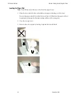
Page 52: ...the edge is loose 1 Place the new roll in the bin with a little extra paper extending over the front Be sure the paper unrolls from the bottom of the roll Otherwise the paper will not be printed on be...

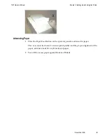
Page 53: ...43 Advancing Paper 1 Press the Paper Feed button on the operator panel to advance the paper The cover must be closed To ensure print quality and the proper alignment of the paper advance about 30 cm...

Page 54: ...ling and Changing the Ribbon Cassette Change the ribbon cassette when the print is too light or the ribbon is frayed Removing the Ribbon Cassette 1 Open the front cover 2 Use the handle on the cassett...

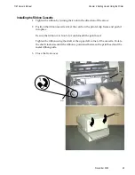
Page 55: ...bbon cassette slot at the catch on the printer slip frame and push it into place Be sure the ribbon is in front of or underneath the print head Tighten the ribbon using the shaft at the upper left cor...

Page 56: ...check check shown in the illustration from the front and place it on the slip table top first and with the print side up If the form is extra long you may need to insert it from the side 2 Slide the...

Page 57: ...7167 Owner s Manual Chapter 2 Setting Up and Using the Printer November 2002 47 Guide Extended Slip Table LED...

Page 58: ...with any preset mark you may have made on the slip table The green LED on the slip table turns on when the form or check is properly inserted it has to cover two sensors on the slip table 4 Follow the...

Page 59: ...7167 Owner s Manual Chapter 2 Setting Up and Using the Printer November 2002 49 LED Guide Extended Slip Table...

Page 60: ...ems that you can easily fix and others that you will need to contact a service representative for You may be able to correct many of the conditions or problems without calling for service However if a...

Page 61: ...e cover The printer will not operate with either of the covers open Knife failure Open the receipt cover and check the knife Clear any jammed paper you can see Tear off any excess paper against the te...

Page 62: ...ove the printer to a cooler location See Environmental Conditions in Appendix A for the recommended temperature range for operating the printer If the print head is overheating because of printing hig...

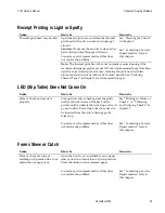
Page 63: ...ermal Paper in chapter 1 for recommended paper LED Slip Table Does Not Come On Problem What to Do Where to Go Form or check not inserted properly Line up the form or check against the guide wall and s...

Page 64: ...er Not Reading Properly Problem What to Do Where to Go MICR Magnetic Ink Character Recognition check reader does not read or misreads checks Open the slip cover and clean the MICR read head with cotto...

Page 65: ...Knife will not cycle or cut Platen will not open or close Printer will not communicate with Host Contacting a Service Representative For serious problems such as the printer not printing not communica...

Page 66: ...oprocessor timing is checked CRC check of the firmware ROM is performed external RAM is read The green LED on the slip table flashes once if this action succeeds Level 0 diagnostics stop if this actio...

Page 67: ...correct settings If you need assistance contact a service representative See Contacting a Service Representative in chapter 3 Printer Configuration Printers are generally shipped with all appropriate...

Page 68: ...lt Lines Per Inch Carriage Return Usage Asian Mode Slip Print Width Receipt Synchronization Setting Hardware Options Print Density Maximum Power Option Paper Low Sensor Paper Width Knife Options MICR...

Page 69: ...ction see Chapter 2 page 13 This configuration menu allows you to set mechanical adjustment parameters and select printer test Sub menus are entered and selections are made using the Paper Feed Button...

Page 70: ...on Errors Receive Buffer Diagnostic Mode Emulation Software Printer Emulation Printer ID Mode Default LPI Printer Config Menu The config menu allows you to set general printer parameters Sub menus are...

Page 71: ...ter to use an RS 232C serial interface the Configuration Menu can be used to set the following RS 232C specific settings Set the baud rate to 115200 57600 38400 19200 9600 4800 2400 or 1200 baud Set t...

Page 72: ...2 Stop Bits Short Click SET PARITY YES Long Click NO Short Click No Parity 1 Click Even Parity 2 Clicks Odd Parity 3 Clicks Enter code then hold Button DOWN At least 1 second to validate SET FLOW CONT...

Page 73: ...prints incoming commands and data in hexadecimal format Slip test Mode the slip printer prints two code pages Receipt Test Mode the receipt printer prints two code pages MICR Test Mode the receipt pr...

Page 74: ...ion Menu exit the Configuration Menu 3 Run a transaction from the host computer All commands and data sent from the host computer will be printed as hexadecimal numbers as shown in the illustration 30...

Page 75: ...ansmitting the values to the software it prints on receipt paper To run the MICR Test Mode 1 Enter the Configuration Menu See Configuring the Printer for instructions on how to enter the Configuration...

Page 76: ...p Test Model 1 Enter the Configuration Menu again 2 Disable the Check Flip Test Mode 3 Exit the Configuration Menu The printer is in Normal Mode and can communicate with the host computer Print Head G...

Page 77: ...de to select additional options Press the Paper Feed Button for the option you want Save new parameters YES Long Click NO MODIFY Short Click Emulation Software Options Printer Emulations Printer emula...

Page 78: ...t the default lines per inch printed by the thermal printer to 6 7 52 or 8 13 See Configuring the Printer for instructions on how to enter the Configuration Menu to change this setting Press the Paper...

Page 79: ...utton for at least one second to validate the selection Slip Printing Width This function allows for the 7197 printer to be set in a mode that allows for the printer to drop the left 21 columns of dat...

Page 80: ...akes it possible to adjust the energy level of the print head to darken the printout An adjustment should only be made when necessary The factory setting is 100 Warning Choose an energy level no highe...

Page 81: ...Disable Paper Low Sensor Short Clicks Note Press the Paper Feed Button for at least one second to validate the selection Paper Width This function allows the user to set the default paper width for th...

Page 82: ...ble MICR Long Disable MICR Short Note Press the Paper Feed Button for at least one second to validate the selection Check Flip Option This function makes it possible to set the Check Flip Option if it...

Page 83: ...Click Save Parameters This function allows to save the selected hardware settings or return to the hardware options to select additional options Press the Paper Feed Button for the option you want Sav...

Page 84: ...ks Code Page 863 3 Clicks Code Page 864 4 Clicks More Options 5 Clicks Enter code then hold Button DOWN At least 1 second to validate Code Page 865 1 Click Code Page 866 2 Clicks Code Page 874 3 Click...

Page 85: ...the Default Settings Caution Be extremely careful changing any of the printer settings to avoid inadvertently changing other settings that might affect the performance of the printer RESET EEPROM TO...

Page 86: ...rint head too hot Power supply voltage out of range Slip or flip motor jam See Chapter 3 Solving Problems for more information about other conditions that may occur and how to correct them Status LED...

Page 87: ...t during the receipt test See Sample Print Test later in this chapter Serial number Model number CRC number Number of receipt lines printed Number of knife cuts Number of slip lines Number of slip cha...

Page 88: ...he printer be able to communicate See the section RS 232C Interface on the next page for a description of the protocol associated with the RS 232C interface Sending Commands Once the communication lin...

Page 89: ...s fast as it is printed This application must also allow receipt lines to be buffered ahead at the printer so the printer can print each line immediately after the preceding line without stopping to w...

Page 90: ...cribed in the next section but it does not look at the DSR signal to transmit data XON character Hex 11 XOFF character Hex 13 DTR DSR Protocol The DTR signal is used to control data transmission to th...

Page 91: ...The illustration shows the RS 232C communication connector and pin assignments The connector is a 9 pin male D shell connector and is located in the hollow cavity under the printer at the rear RS 232...

Page 92: ...ype B communication connector and pin assignment Pin No Signal 1 5 V USB 2 Data 3 Data 4 Ground Power Cable Connector The illustration shows the power cable connector and pin assignments The power cab...

Page 93: ...for the cash drawer connectors The following table provides the pinout assignments for cash drawers one and two The cash drawer connectors are located at the rear of the printer Pin 1 Pin 6 Pin Numbe...

Page 94: ...e switches to the desired settings shown in the table 2 Reset the printer Caution Setting switch 1 to On puts the printer in level 1 diagnostics setup mode where other functions and tests can be chang...

Page 95: ...that may be available in other printers but are not available in this printer some commands will be listed and described but identified as not implemented If the printer receives one of these not imp...

Page 96: ...nce 168 11 Close Form 91 12 Select Double Wide Characters 122 13 Select Single Wide Characters 122 14 n Feed n Print Lines 106 15 n Feed n Dot Rows 107 16 n Add n Extra Dot Rows 107 17 Print 108 18 Op...

Page 97: ...or Cancel Emphasized Mode 131 1B 47 Select Double Strike 7156 Emulation 132 1B 48 Cancel Double Strike 133 1B 49 n Set or Cancel Italic Print 133 1B 4A n Print and Feed Paper 110 1B 4B n Print and Re...

Page 98: ...191 1B 77 46 Check Flip 200 1B 77 50 Define Parsing Format Save in NVRAM 192 1B 77 52 Reread MICR Data 191 1B 77 70 Define Parsing Format Do Not Save Permanently 192 1B 7A n Select or Cancel Parallel...

Page 99: ...d Macro Definition 189 1D 40 n Erase User Flash Sector 205 1D 42 n Select or Cancel White Black Reverse Print Mode 138 1D 48 n Select Printing Position for HRI Characters 175 1D 49 n Transmit Printer...

Page 100: ...Command Code and Operands Command Name Page 1F 04 n Convert 6 Dots mm Bitmap to 8 Dots mm Bitmap 150 1F 05 n Select Superscript or Subscript Modes 139 IF 11 m n m n m n 0FFH Printer Setting Change 20...

Page 101: ...lip for Printing Slip for MICR Read 94 1B 63 31 n Select Receipt or Slip for Setting Line Spacing 96 1B 63 34 n Select Sensors to Stop Printing 97 1B 63 35 n Enable or Disable Panel Buttons 98 1B 63 3...

Page 102: ...B 4A n Print and Feed Paper 110 1B 4B n Print and Reverse Feed Paper 111 1B 64 n Print and Feed n Lines 112 1B 65 n Print and Reverse Feed n Lines 111 1D 14 n Reverse Feed n Lines 112 1D 15 n Reverse...

Page 103: ...Copy Character Set from ROM to RAM 130 1B 3F n Cancel User Defined Characters 131 1B 45 n Select or Cancel Emphasized Mode 131 1B 47 Select Double Strike 7156 Emulation Mode 132 1B 47 n Select Double...

Page 104: ...hics 146 1D 23 n Select Current Logo Downloaded Bit Image 146 1D 2A n1 n2 d1 dn Define Downloaded Bit Image 147 1D 2F m Print Downloaded Bit Image 149 1F 04 n Convert 6 Dots mm Bitmap to 8 Dots mm Bit...

Page 105: ...me Status Transmission GS Sequence 165 1D 05 Real Time Printer Status Transmission 170 Auto Status Back Commands Hexadecimal Command Code and Operands Command Page 1D 61 n Select or Cancel Auto Status...

Page 106: ...de 186 1D 24 nL nH Set Absolute Vertical Print Position in Page Mode 187 1D 5C nL nH Set Relative Vertical Print Position in Page Mode 188 Macro Commands Hexadecimal Command Code and Operands Command...

Page 107: ...1 n2 k Write to Non Volatile Memory NVRAM 202 1D 22 n Select Memory Type SRAM Flash Where to Save Logos or User Defined Fonts 203 1D 22 55 n1 n2 Flash Allocation 204 1D 40 n Erase User Flash Sector 20...

Page 108: ...t Printer ID 213 1D 01 Return Segment Number Status of Flash Memory 214 1D 02 n Select Flash Memory Sector to Download 214 1D 06 Get Firmware 215 1D 07 Return Microprocessor CRC 215 1D 0E Erase the Fl...

Page 109: ...ontal motion units By default these units are in terms of 1 203 inches versus 1 152 inches 1B 24 n1 n2 Set Absolute Starting Position For graphics commands the position is scaled to best match the pre...

Page 110: ...the command moves and aligns to character positions In 7156 Emulation Mode this command calculates how many character positions to move based on the 7156 s character width in dots 10 versus the 7167 s...

Page 111: ...tation of the command control code followed by its operands Decimal The decimal representation of the command control code followed by its operands Operand n A description of the command operand Other...

Page 112: ...line buffer without printing and sets the printer to the following condition 1 Receipt station is selected 2 Double Wide command 0x12 is cancelled 3 Line Spacing Pitch and User Defined Character Sets...

Page 113: ...essed regardless of which station is selected Example MSComm1 Output Chr H11 Open Form ASCII CAN Hexadecimal 18 Decimal 24 When the printer is in 7156 Emulation Mode or in non Page Mode this command o...

Page 114: ...lected Example MSComm1 Output Chr H19 or MSComm1 Output Chr H1B Chr H69 Perform Partial Knife Cut ASCII SUB or ESC m Hexadecimal 1A or 1B 6D Decimal 26 or 27 109 Cuts the receipt leaving 20 inch 5 mm...

Page 115: ...utput Chr H1B Chr H07 Return Home ASCII ESC Hexadecimal 1B 3C Decimal 27 60 Moves the impact print head unless it is already in the home position to the home position This command is processed regardl...

Page 116: ...buffer and resets the printer to the default settings for the startup configuration refer to Default settings above Single Wide Single High Non Rotated and Left Aligned characters are set and User def...

Page 117: ...e slip waiting time setting ie 1B 66 m n for the paper to be inserted When the slip station has already been selected and the selection is changed the form feed roller is opened If the station has alr...

Page 118: ...receipt 4 Select Slip Default of n 1 Selects which station receives the effects of the following commands 1 Select Default Line Spacing 1B 32 2 Set Line Spacing 1B 33 3 Add n extra dot rows 16 n Exam...

Page 119: ...ng Edge Uncovered Default 0 Determines which sensor causes the printer to stop printing on the respective station The command does not affect the paper out sensor on the receipt station which will aut...

Page 120: ...the Paper Feed Button If the last bit is 0 the Paper Feed Button is enabled If the last bit is 1 the Paper Feed Button is disabled so pressing the paper feed button will result in no response Example...

Page 121: ...nables or disables the the slip paper end feeding stop function When this feature is enabled the printer will print a line but will not perform a line feed when the slip paper end is detected Example...

Page 122: ...start printing once the slip has been inserted The printer reads that a slip is inserted when the leading edge and trailing edge sensors are covered The LED on the slip table is lit green when both s...

Page 123: ...to open the cash drawer Formulas The value for either p1 or p2 is the hexadecimal number multiplied by 2 msec to equal the total time 1 On time p1 x 2 msec 2 Off time p2 x 2 msec Example MSComm1 Outp...

Page 124: ...Decimal 28 Selects the Slip Station for all functions The receipt station is the default setting after the printer is initialized or the Clear Printer 0x10 command is received The Hex command 1B 63 3...

Page 125: ...cut Range of m 0 48 1 49 65 66 when used with n Range of n 0 255 Default of n 0 Default of m 0 Selects a mode for cutting paper and cuts the paper There are two formats for this command one requiring...

Page 126: ...efault setting after the printer is initialized or the Clear Printer 0x10 command is received The Hex command 1B 63 30 n where n 1 2 3 will also select the receipt station Example MSComm1 Output Chr H...

Page 127: ...nly one line Print and Eject Slip ASCII FF Hexadecimal 0C Decimal 12 Prints data from the buffer to the slip station and if the paper sensor is covered reverses the slip out the front of the printer f...

Page 128: ...Example MSComm1 Output Chr H0D Related Information See Ignoring Using the Carriage Return in Diagnostics for more information Carriage Return Line Feed prints and feeds only one line Feed n Print Line...

Page 129: ...ws if the print buffer is empty Example MSComm1 Output Chr H15 Chr n Add n Extra Dot Rows ASCII SYN n Hexadecimal 16 n Decimal 22 n Value of n Receipt Slip n 203 inch n 72 inch Range of n 0 12 Default...

Page 130: ...0 4 7 25 28 4 6 55 11 5 7 00 29 5 6 00 12 6 6 77 30 6 5 54 13 7 6 55 31 7 5 14 14 8 6 35 32 8 4 80 15 9 6 16 33 9 4 50 16 10 5 98 34 10 4 24 17 11 5 81 35 11 4 00 18 12 5 64 36 12 3 79 19 Example MSCo...

Page 131: ...extra dot rows Slip 14 inch 7 2 lines per inch 3 extra dot rows Sets the line spacing for the receipt and for the slip For the receipt the spacing is set to n 406 inches For the slip the line spacing...

Page 132: ...line of the slip at 59 inches from the trailing edge and still retain the slip in the feed rollers for reverse feeding the paper back out of the slip station Example MSComm1 Output Chr H1B Chr H4A Chr...

Page 133: ...e from the buffer and feeds paper n lines at the current line height Example MSComm1 Output Chr H1B Chr H64 Chr n Print and Reverse Feed n Lines ASCII ESC e n Hexadecimal 1B 65 n Decimal 27 101 n Valu...

Page 134: ...ed back to the normal feed direction This command is ignored if slip is not the selected station Current spacing is not a factor Example MSComm1 Output Chr H1D Chr H14 Chr n Reverse Feed n Dots ASCII...

Page 135: ...f y Vertical Range of x 0 255 Range of y 0 255 Default of x 203 Default of y 203 Sets the horizontal and vertical motion units to 1 x inch and 1 y inch respectively When x or y is set to 0 the default...

Page 136: ...line Tab treats the left margin as column one therefore changes to the left margin will move the tab positions When there are no tabs defined to the right of the current position or if the next tab i...

Page 137: ...ng of the line The print starting position is reset to the first column after each line Formulas Determine the value of n by multiplying the column for the absolute starting position by 10 slip or rec...

Page 138: ...the Horizontal Tab 09 command The tab positions remain unchanged if the character widths are changed after the tabs are set This command ends with hexadecimal 00 hexadecimal 1B 44 00 clears all tabs...

Page 139: ...s reset to the first column after each line Formulas To move to the left Determine the value of n by multiplying the number of columns to move left of the current position by 13 receipt standard pitch...

Page 140: ...g allows the 7156 to backup in the print string and replace characters and their associated attributes when a Set Relative Print Position command instructs the printer to move the print position to th...

Page 141: ...ich follows this command See the Set Printing Area Width command 1D 57 in this document for a description of that command If the setting exceeds the printable area the maximum value of the printable a...

Page 142: ...hes The horizontal motion units are set by the Set Horizontal and Vertical Minimum Motion Units command 1D 50 The width of the printing area follows the Set Left Margin command 1D 4C See the Set Left...

Page 143: ...r is not empty and only effects the Receipt interface If the setting exceeds the printable area the maximum value of the printable area is used The maximum printable area is 576 dots for 80 mm paper w...

Page 144: ...Wide Characters ASCII DC2 Hexadecimal 12 Decimal 18 Prints double wide characters The printer is reset to single wide mode after a line has been printed or the Clear Printer 0x10 command is received...

Page 145: ...received Example MSComm1 Output Chr H1B Chr H12 Exceptions This command is valid only at the beginning of a line Rotated print and non rotated print characters cannot be used together in the same lin...

Page 146: ...I Slip Columns Slip CPI Standard 44 for 80 mm paper 15 6 45 13 9 32 for 58 mm paper Compressed 56 for 80 mm paper 20 3 55 17 1 42 for 58 mm paper Example MSComm1 Output Chr H1B Chr H16 Chr n Related I...

Page 147: ...zontal and Vertical Minimum Motion Units 1D 50 command the value must be in even units and not less than the minimum amount of horizontal movement In Standard Mode the horizontal motion unit is used I...

Page 148: ...ne 80 mm 42 Col Line 58 mm 17 1 CPI Slip 55 Col Line Bit 3 Emphasized Mode Canceled Set Bit 4 Double high2 Canceled Set Bit 5 Double wide Canceled Set Bit 7 Underlined Mode Canceled Set Bits 1 2 6 are...

Page 149: ...rline Select or Cancel User Defined Character Set ASCII ESC n Hexadecimal 1B 25 n Decimal 27 37 n Value of n 0 Code Page 437 1 User defined RAM character set 2 Code Page 850 Range 0 2 Default 0 Code P...

Page 150: ...ble until power is turned off or the Initialize Printer command 1B 40 is received Any invalid byte s c1 c2 n1 aborts the command User defined character sets for both slip and receipt may be used at th...

Page 151: ...th character as specified by d1 dn The number of bytes for a particular character cell is 3 x n1 The bytes are printed down and across each cell Slip c the ASCII codes of the first c1 and last c2 char...

Page 152: ...1 turn underline on and off in the same way Example MSComm1 Output Chr H1B Chr H2D Chr n Exceptions This command is ignored if n is out of the specified range This command is only available in 7158 Na...

Page 153: ...corresponding pattern from Code Page 437 is printed Example MSComm1 Output Chr H1B Chr H3F Chr n Exceptions This command is ignored if n is out of range or if the user defined character is not defined...

Page 154: ...line on the slip station to improve penetration of multi part forms and increase print contrast The second pass is printed the same direction as the first to ensure accuracy of the overprint The print...

Page 155: ...t or Cancel Italic Print ASCII ESC I n Hexadecimal 1B 49 n Decimal 27 73 n Value of n 0 Off 1 On When 0 and 1 are the Least Significant Bit LSB Default 0 Off Turns Italic print mode on or off This com...

Page 156: ...e Page 437 1 Code Page 850 Multilingual 1 Code Page 850 2 Code Page 852 Slavic 3 Code Page 860 Portuguese 4 Code Page 863 French Canadian 5 Code Page 865 Nordic 6 Code Page 858 Multilingual with Euro...

Page 157: ...Character Set Select or Cancel Unidirectional Printing Mode ASCII ESC U n Hexadecimal 1B 55 n Decimal 27 85 n Value of n 0 select bi directional 1 select unidirectional Default 0 bi directional Toggl...

Page 158: ...elects color printing Color printing is valid for character graphics logo and barcodes Example MSComm1 Output Chr H1B Chr H72 Chr n Exceptions The command is valid only for receipt station Select or C...

Page 159: ...n Value of n 1 8 vertical number of times normal font 1 8 horizontal number of times normal font Range of n 00 07 10 17 70 77 Default of n 0 Selects the character height using bits 0 to 2 and selects...

Page 160: ...and horizontal directions is reversed In Page Mode vertical and horizontal directions are based on the character orientation When characters are enlarged with different sizes on one line all the chara...

Page 161: ...loaded bit image bar code HRI characters and spacing skipped by Horizontal Tab 09 Set Absolute Starting Position 1B 24 and Set Relative Print Position 1B 5C White Black reverse mode has a higher prior...

Page 162: ...h other characters size settings commands 12 13 1B 21 n 1D 21 n This command is only available on the receipt station in 7158 Native Mode and 7167 Native Mode Example MSComm1 Output Chr H1F Chr H05 Ch...

Page 163: ...show only the normal size characters Double wide and double high characters are printed in the same orientation double high characters cannot be printed on the slip station They may also be mixed on...

Page 164: ...inted by using the Print Downloaded Bit Image 1D 2F m command Example 1 MSComm1 Output Chr H1B 2 Open bitmapfile For Binary As filehandle 3 filecontent Input LOF filehandle filehandle 4 MSComm1 Output...

Page 165: ...ation of the bit image In 7156 Emulation Mode slip graphics are only 7 bit MSB not printed In 7158 Native Mode and 7167 Native Mode slip graphics are 8 bit Values Receipt Station Value of m Mode No of...

Page 166: ...ll dot column Adjacent horizontal dots overlapping dots are not printed on the slip In 7158 Native Mode and 7167 Native Mode There are 8 vertical dots Value of n 8 Dot Single Density Mode Value of n 2...

Page 167: ...7167 Owner s Manual Chapter 6 Commands November 2002 145 Top of Bit Image 24 Dot Single Density Mode Receipt Only dn MSB LSB d1 d2 d3 d4 d7 d5 d6 dn...

Page 168: ...nge of n 0 255 Selects a logo to be defined or printed The active logo n remains in use until this command is sent again with a different logo n When this command precedes a logo definition that defin...

Page 169: ...tation is currently selected Define Downloaded Bit Image ASCII GS n1 n2 d1 dn Hexadecimal 1D 2A n1 n2 d1 dn Decimal 29 42 n1 n2 d1 dn Value of n1 See the following table Value of n2 See the following...

Page 170: ...Bit Image command 1D 2F for a representation of the bit image Related Information See 1D 22 n Select Memory Type to store logos and 1D 23 n Select the Current Logo For the 7158 native mode and 7167 N...

Page 171: ...rints a downloaded bit image in RAM or Flash on the receipt station at a density specified by m It is ignored if any data is in the print buffer if the downloaded bit image is undefined or if the data...

Page 172: ...dot mm in 7158 Emulation Mode and 7167 Native Mode When the 6 dot mm emulation is selected logos and graphics are expanded horizontally and vertically to emulate their size on a 6 dot mm printer The h...

Page 173: ...eir response if any is returned to the application This gives the application the ability to query the printer when it is in a busy state in order to correct whatever fault has occurred Auto Status Ba...

Page 174: ...1 Return Value 1 Drawer 1 closed 1 Drawer 2 closed 0 Drawer 1 open 0 Drawer 2 open Bits 2 7 are not used Transmits current status of the cash drawers One byte is sent to the host computer In DTR DSR p...

Page 175: ...waits for DSR SPACE Status Byte RS 232C Bit Function 0 Signifies 1 Signifies 0 Receipt Paper Ok Low 1 Receipt Cover or Front Cover Closed Open 2 Receipt Paper Ok Out 3 Knife or Slip Ok Jam 4 Always Z...

Page 176: ...ative Mode 1 49 Printer model ID NCR 7156 0x26 7156 Emulation 1 49 Printer model ID NCR 7150 0x02 7150 Mode 2 50 Type ID Installed options Refer to the table below 3 51 ROM version ID ROM version 0x00...

Page 177: ...diagnostic function specified by n Eighteen remote diagnostic items are defined eight printer ID items and ten printer tally items A group of four remote diagnostic functions is assigned to each diagn...

Page 178: ...int on receipt to verify 27 39 Class model Return Class model returns 17 bytes 2B 43 Boot firmware part 12 digit ASCII Return Boot firmware part returns 14 bytes 2F 47 Boot firmware CRC 4 digit ASCII...

Page 179: ...MICR read tally 8 digit ASCII numeric max 99 999 999 Write to NVRAM 8D 141 MICR read tally Write to NVRAM and print on receipt to verify 8E 142 MICR read tally Clear MICR read tally to 0 8F 143 MICR r...

Page 180: ...meric max 99 999 999 Write to NVRAM AD 173 Cover openings tally Write to NVRAM and print on receipt to verify AE 174 Cover openings tally Clear Cover openings tally to 0 AF 175 Cover openings tally Re...

Page 181: ...g on the receive buffer status When DTR DSR RS232C communications handshaking control is selected the printer transmits the one byte response only when the host signal DSR indicates it is ready to rec...

Page 182: ...used Fixed to off Cash Drawer Status n 2 or n 50 Bit Off On Hex Decimal Status for Transmit Status 0 Off On 00 01 0 1 One or both cash drawers open Both cash drawers closed 1 Off On 00 02 0 2 One or...

Page 183: ...Thermal user defined characters written to Flash 6 Off On 00 04 0 64 No impact user defined characters written to Flash Impact user defined characters written to Flash 7 Off 00 0 Not used Fixed to off...

Page 184: ...rive in the order in which they were solicited Batch Mode Response Response Recognized By ASCII HEX ESC u 0 1B 75 0 0 0 0 0 0 0 x x Binary ESC v 1B 76 0 0 0 0 0 x x x Binary GS I n 1D 49 n 0 x x 0 x x...

Page 185: ...on the GS 1D sequences are recommended to avoid possible misinterpretation of a DLE 0x10 sequence as a Clear Printer 0x10 0 ASCII DLE NUL command An application using these GS 1D sequences does not ne...

Page 186: ...nd any other data there and flush them out in the order in which they were received When the printer is busy due simply to buffer full that is it can t print data as fast as it can receive it then dat...

Page 187: ...the selected one byte printer status specified by n in Real Time according to the following parameters This command includes two sequences GS and DLE and using either or will produce the same result E...

Page 188: ...ed to On 5 Undefined 6 Undefined 7 Off 00 0 Fixed to Off 2 Transmit RS 232C Busy Status Bit Status Hex Decimal Function 0 Off 00 0 Fixed to Off 1 On 02 2 Fixed to On 2 Off On 00 04 0 4 Both receipt an...

Page 189: ...curred 6 Off On 00 40 0 64 Thermal print head temp power supply voltage are in range Thermal print head temp power supply voltage are out of range 7 Off 00 0 Fixed to Off 4 Transmit Receipt Paper Stat...

Page 190: ...r and restart 2 Recover and clear buffers 3 Cancel slip waiting The printer responds to a request from the host specified by n This command includes two sequences GS and DLE The operations performed d...

Page 191: ...ip was selected when the error occurred the receipt becomes selected when the buffers are cleared When printing on the slip is to continue the slip must be selected again The same error recovery possi...

Page 192: ...aper adequate Receipt paper low 2 Off On 00 04 0 4 Both receipt and cassette doors closed Receipt or cassette door open 3 Off On 00 08 0 8 Not busy at the RS 232C interface Printer is busy at the RS 2...

Page 193: ...ected status changes If no status is selected ASB is disabled All four status bytes are transmitted without checking DSR If the error status is enabled a change in the following conditions will trigge...

Page 194: ...d are described in the following four tables Byte 1 printer information Byte 2 error information Byte 3 paper sensor information Byte 4 paper sensor information First Byte Printer Information Bit Off...

Page 195: ...paper exhausted Thermal print head temp out of range Power supply voltage out of range 7 Off 00 0 Not used Fixed to off Third Byte Paper Sensor Information Bit Off On Hex Decimal Status for ASB 0 Off...

Page 196: ...Decimal Status for ASB 0 Off On 00 01 0 1 Slip paper selected Receipt paper selected 1 Off On 00 02 0 2 Possible to print in slip Not possible to print on slip because no form has been inserted 2 Und...

Page 197: ...the narrow modules The default is 3 DPM 7167 firmware ranges from 1 dot per module to 5 dots per module DPM printed on the receipt The default is 2 DPM Select Printing Position for HRI Characters ASCI...

Page 198: ...t 15 2 CPI Selects standard or compressed font for printing Bar Code characters When slip is selected as the interface HRI is always compressed Example MSComm1 Output Chr H1D Chr H66 Chr n Select Bar...

Page 199: ...the second uses a length byte at the beginning of the string to compensate for the Code 128 bar code which can accept a NUL character as part of the data With the second variation the length of byte...

Page 200: ...6 43 45 46 47 58 Variable Length 10 PDF 417 7158 Native Mode and 7167 Native Mode 1 255 Variable Length 7158 Native Mode and 7167 Native Mode Second Variation Length of Byte Specified at Beginning of...

Page 201: ...72 Code 93 0 127 Variable 7158 Native Mode and 7167 Native Mode only 73 Code 128 0 105 d1 103 105 must be a Start code d2 0 102 data bytes Stop code is provided by the printer Variable 75 PDF417 0 25...

Page 202: ...119 n Value of n 1 2 3 4 5 Default 3 for receipt 2 for slip Sets the bar code width to n dots Formulas n 1 8 mm n 1 203 inch for receipt n 1 5 7 mm n 1 144 inch for slip Slip module sizing n must be e...

Page 203: ...Mode command 1B 4C puts the printer into Page Mode Any commands that are received are interpreted as Page Mode commands Several commands react differently when in Standard Mode and Page Mode The desc...

Page 204: ...formed when the printer is not in Page Mode Example MSComm1 Output Chr H18 Exceptions This command is only used in Page Mode Print Data in Page Mode ASCII ESC FF Hexadecimal 1B 0C Decimal 27 12 Collec...

Page 205: ...ependently in Standard Mode and Page Mode to those for Page Mode 1 Set Right Side Character Spacing 1B 20 2 Select 1 6 Inch Line Spacing 1B 32 3 Set Line Spacing 1B 33 4 It is possible only to set val...

Page 206: ...is set to the beginning of the line This command switches the settings for the following commands the values for these commands can be set independently in Standard Mode and Page Mode to those for St...

Page 207: ...C and D note the direction of of print See illustration Selects the printing direction and start position in Page Mode See the illustration The command can be sent multiple times so that several diff...

Page 208: ...ion is set to dy inches The length of the area to be printed in the x direction is set to dx inches Use the equations to determine the Value of x0 y0 dx and dy See the illustration for a graphic repre...

Page 209: ...by Select Print Direction in Page Mode 1B 54 This sets the absolute position in the vertical direction when the starting position is set to the upper left or lower right and sets the absolute positio...

Page 210: ...he upper right or lower left of the printing area the horizontal motion unit x is used Value The value for the horizontal and vertical movement cannot be less than the minimum horizontal movement amou...

Page 211: ...nting occurs while the macro is defined When the power is turned on the macro is not defined The defined contents of the macro are not cleared by the Initialize Printer 1B 40 thus the Initialize Print...

Page 212: ...he Paper Feed Button to be pressed After the button is pressed the printer executes the macro once The printer repeats this operation the number of specified times When the macro is executed by pressi...

Page 213: ...ble Read MICR Data and Transmit ASCII ESC w 1 Hexadecimal 1B 77 01 Decimal 27 119 1 Default All data returned Reads and transmits the MICR data and adds a Carriage Return 0x0D If no parsing format is...

Page 214: ...parse string The string must be CR terminated If the string has invalid characters in it or is too long the printer will store a null string and raw MICR data will be returned See sample parsing examp...

Page 215: ...2 digit ASCII number Remove space dash X Replace space dash with 0 x Examples of Variable Length Field Format Specifications Account all characters in the field keep spaces and dashes A Account all c...

Page 216: ...k Ten parameters are more than enough to specify all variable length fields with a field separator each and other status information that may be helpful to an application More than 10 parameters are n...

Page 217: ...ESC w p 018 X A CR Always 18 characters in the account number with spaces and dashes removed Final Carriage Return ESC w p 018 x A CR Always 18 characters in the account number with spaces and dashes...

Page 218: ...parameter string is the order in which the parsed MICR data will be returned Unrecognized parameters will be ignored and processing of the parsing parameters will stop Any data remaining after the unr...

Page 219: ...e a three or more digit number to the right of the rightmost on us symbol and to the left of the leftmost amount symbol if an amount field is present is the check serial number txxxxxxxxxt xxxxxxxxo c...

Page 220: ...ithout an exception table entry the firmware would not be able to pick out the check serial number correctly because it is imbedded within the rest of the account number txxxxxxxxxt xxx ccc xxxxxxxxxx...

Page 221: ...table entry using 0x1B 0x73 0x24 0x4A 27 0x1B 0x73 0x00 0x00 28 0x1B 0x73 0x00 0x00 29 Example 2 t22137 632t001 6042202o927540 2754 is the check serial 6042202 is the account To load the third table...

Page 222: ...B to be flipped If not the check is fed back to the user Example MSComm1 Output Chr H1B Chr H77 Chr H46 Exception This command is available only in 7158 Native Mode and 7167 Native Mode User Data Stor...

Page 223: ...m User Data Storage ASCII ESC 4 m a0 a1 a2 Hexadecimal 1B 34 m a0 a1 a2 Decimal 27 52 m a0 a1 a2 Value of m 0 255 Reads m bytes of data from the User Data Storage Flash Page at the address specified E...

Page 224: ...istory EEROM The printer returns the word at the next available opportunity Example MSComm1 Output Chr H1B Chr H6A Chr k Write to Non Volatile Memory NVRAM ASCII ESC s n1 n2 k Hexadecimal 1B 73 n1 n2...

Page 225: ...is is the default condition for logo Flash storage A logo defined following this command is stored in Flash Memory n 50 ASCII n 2 Loads user defined characters to RAM only This is the default conditio...

Page 226: ...tion of Flash sectors between user data storage and logos user defined characters This allocation is saved in the EEPROM of the printer and is therefore saved across power cycles n1 n2 6 3M The 7167 h...

Page 227: ...nother In both cases all logos and character set definitions are erased and must be redefined n 50 ASCII n 2 This command erases all sectors available for user data storage Important While erasing Fla...

Page 228: ...bps 19200 bps 9600 bps 4800 bps 2400 bps 1200 bps 12 Number of data bit 00 01 8 data bits 7 data bits 13 Number of stop bit 00 01 1 stop bits 2 stop bits 14 Parity 00 01 No parity Even parity Odd pari...

Page 229: ...ption 00 01 82 2 mm 7167 Mode 120 7 Conversion 7156 58 Mode 25 Receipt synchronization 00 01 Enabled Disabled 30 Print density 00 01 02 100 110 120 31 Paper Low sensor option 00 01 Paper low sensor en...

Page 230: ...932 or 936 949 950 50 EEPROM default setting 00 EEPROM default setting Set the printer configuration specified by m and n The printer is reset after receiving this command to activate the configuratio...

Page 231: ...width mode is not selected Double width mode is selected 3 Off On 00 01 0 1 Double height mode is not selected Double height mode is selected 4 Undefined 5 Undefined 6 Undefined 7 Off On 00 01 0 1 Und...

Page 232: ...Asian character All characters could be underlined including character right side spacing Underline can be selected by FS and ESC also the last received command is effective Example MSComm1 Output Ch...

Page 233: ...definition The maximum number of user defined character is 100 Example MSComm1 Output Chr H1C Chr H32 Chr HF0 Chr H40 Chr d1 Chr dn Set Kanji character spacing ASCII FS S n1 n2 Hexadecimal 1C 53 n1 n...

Page 234: ...28 87 n Value of n The quadruple mode for Asian characters 0 Bit 0 Quadruple mode off 1 Bit 0 Quadruple mode on Default of n 0 Quadruple mode off Selects or cancels the quadruple mode for Asian charac...

Page 235: ...l printer operation either the operator must turn the power off and then on to reboot or the application must send a command to cancel Download Mode and reboot Switch to Flash Download Mode ASCII ESC...

Page 236: ...MSComm1 Output Chr H1D Chr H01 Exceptions Available only in Download Mode Select Flash Memory Sector to Download ASCII GS STX n Hexadecimal 1D 02 n Decimal 29 2 n Value of n The Flash sector to which...

Page 237: ...s The printer transmits ACK if the calculated CRC is correct for the selected sector NAK if the CRC is incorrect or if no sector is selected Example MSComm1 Output Chr H1D Chr H06 Return Microprocesso...

Page 238: ...le MSComm1 Output Chr H1D Chr H0F Erase Selected Flash Sector ASCII GS DLE n Hexadecimal 1D 10 n Decimal 29 16 n Value and Range of n 0 7 512K bytes Flash 0 15 1M bytes Flash 0 31 2M bytes Flash Erase...

Page 239: ...ny bytes The start address is relative to the start of the sector Addresses run from 0 to 64K The printer may return one of several responses ACK means that the data was written correctly and the host...

Page 240: ...printer should have firmware loaded and external switches set to the runtime settings Application software for downloading should prompt the user to set the external switches and confirm before sendin...

Page 241: ...For 80 mm paper 44 Columns Standard 56 Columns Compressed For 58 mm paper 32 Columns Standard 42 Columns Compressed 45 Columns Standard 55 Columns Compressed Print Mode Standard Compressed Double Hig...

Page 242: ...w Speed 6 7 Inches per Second 4 0 lines per Second Print Zone 2 83 Inches Maximum 3 23 Inches Maximum Noise 57 dBA Sound Pressure ISO 7779 62 dBA Sound Pressure ISO 7779 Graphics Optional User Defined...

Page 243: ...s Max 3 22 Inches Max Power Requirements The 7167 printer receives power from a separate power supply Here are the voltage requirements for the power supply Maximum Current Voltage Station Short Term...

Page 244: ...7167 Owner s Manual Appendix A Specifications November 2002 214...

Page 245: ...Weight 4 50 Kg 10 0 Pounds Flip Model 4 25 Kg 9 4 Pounds Non Flip Model Density of Receipt Print Lines When the receipt station prints high density print lines graphics it automatically slows down to...

Page 246: ...rinting 3 Reduce the ambient temperature Ambient Temperature Amount of Solid Coverage 25 C 35 C 50 C 20 100 of 1 min continuous printing 50 of 1 min continuous printing 20 of 1 min continuous printing...

Page 247: ...eipt and slip stations Receipt Station The following two illustrations show the dot patterns of sample characters for standard pitch 15 6 CPI and compressed pitch 20 3 CPI Note that compressed pitch u...

Page 248: ...ns for compressed pitch The second illustration shows the layout of columns for standard pitch characters D C A B E Next Character Row spacing is fixed and column spacing depends upon the character pi...

Page 249: ...increments depending upon pitch but the printer cannot print overlapping dots on a single print row No ASCII character contains overlapping dots on a print row Double Wide Characters Double wide char...

Page 250: ...aracters in a 5x7 dot format printed 90 degrees counterclockwise as shown in the illustration or clockwise Only one horizontal pitch is available 6 95 CPI 33 columns maximum Dimension Horizontal Pitch...

Page 251: ...e height is 27 dots 3 38 mm 133 inches for characters with three extra dot rows See the following illustration not to scale For 58 mm Paper The receipt station centers characters standard pitch and co...

Page 252: ...characters is 2 46 mm 097 in With three dot spacing the print line height is 3 53 mm 139 inches See the following illustration not to scale To print as close to the bottom of the slip as possible with...

Page 253: ...affected by gluing method and the quality of glue used when form is glued on the right or top edge of form 3 Skewing may occur when the form is glued on the left edge or when a wide form is used The s...

Page 254: ...O 1004 Forms Checks must be flat and void of curls folds or wrinkles expecially at the leading edges of the checks Paper jams and MICR read errors will occur if check have paper clips and staples Also...

Page 255: ...e Page 850 Multilingual PC Code Page 852 Slavic PC Code Page 860 Portuguese PC Code Page 862 Hebrew PC Code Page 863 French Canadian PC Code Page 864 Arabic PC Code Page 865 Nordic PC Code Page 866 Cy...

Page 256: ...7167 Owner s Manual Appendix C November 2002 226 Code Page 950 Code Page 437 850 852 and 858...

Page 257: ...7167 Owner s Manual Appendix C November 2002 227 Code Page 860 862 863 and 864...

Page 258: ...7167 Owner s Manual Appendix C November 2002 228 Code Page 865 866 874 and 1252...

Page 259: ...7167 Owner s Manual Appendix C November 2002 229 Code Page Katakana...

Page 260: ...7167 Owner s Manual Appendix C November 2002 230 Code Page 932...

Page 261: ...7167 Owner s Manual Appendix C November 2002 231 Code Page 932 Cont...

Page 262: ...7167 Owner s Manual Appendix C November 2002 232 Code Page 932 Cont...

Page 263: ...7167 Owner s Manual Appendix C November 2002 233 Code Page 932 Cont...

Page 264: ...7167 Owner s Manual Appendix C November 2002 234 Code Page 932 Cont...

Page 265: ...7167 Owner s Manual Appendix C November 2002 235 Code Page 932 Cont...

Page 266: ...7167 Owner s Manual Appendix C November 2002 236 Code Page 932 Cont...

Page 267: ...7167 Owner s Manual Appendix C November 2002 237 Code Page 932 Cont...

Page 268: ...7167 Owner s Manual Appendix C November 2002 238 Code Page 932 Cont...

Page 269: ...7167 Owner s Manual Appendix C November 2002 239 Code Page 936 Simple Chinese...

Page 270: ...7167 Owner s Manual Appendix C November 2002 240 Code Page 936 Simple Chines1e Cont...

Page 271: ...7167 Owner s Manual Appendix C November 2002 241 Code Page 936 Simple Chinese Cont...

Page 272: ...7167 Owner s Manual Appendix C November 2002 242 Code Page 936 Simple Chinese Cont...

Page 273: ...7167 Owner s Manual Appendix C November 2002 243 Code Page 936 Simple Chinese Cont...

Page 274: ...7167 Owner s Manual Appendix C November 2002 244 Code Page 936 Simple Chinese Cont...

Page 275: ...7167 Owner s Manual Appendix C November 2002 245 Code Page 936 Simple Chinese Cont...

Page 276: ...7167 Owner s Manual Appendix C November 2002 246 Code Page 936 Simple Chinese Cont...

Page 277: ...7167 Owner s Manual Appendix C November 2002 247 Code Page 936 Simple Chinese Cont...

Page 278: ...7167 Owner s Manual Appendix C November 2002 248 Code Page 936 Simple Chinese Cont...

Page 279: ...7167 Owner s Manual Appendix C November 2002 249...

Page 280: ...7167 Owner s Manual Appendix C November 2002 250 Code Page 936 Simple Chinese Cont...

Page 281: ...7167 Owner s Manual Appendix C November 2002 251 Code Page 949 Korean...

Page 282: ...7167 Owner s Manual Appendix C November 2002 252 Code Page 949 Korean Cont...

Page 283: ...7167 Owner s Manual Appendix C November 2002 253 Code Page 949 Korean Cont...

Page 284: ...7167 Owner s Manual Appendix C November 2002 254 Code Page 949 Korean Cont...

Page 285: ...7167 Owner s Manual Appendix C November 2002 255 Code Page 949 Korean Cont...

Page 286: ...7167 Owner s Manual Appendix C November 2002 256 Code Page 949 Korean Cont...

Page 287: ...7167 Owner s Manual Appendix C November 2002 257 Code Page 949 Korean Cont...

Page 288: ...7167 Owner s Manual Appendix C November 2002 258 Code Page 949 Korean Cont...

Page 289: ...7167 Owner s Manual Appendix C November 2002 259 Code Page 949 Korean Cont...

Page 290: ...7167 Owner s Manual Appendix C November 2002 260 Code Page 949 Korean Cont...

Page 291: ...7167 Owner s Manual Appendix C November 2002 261 Code Page 949 Korean Cont...

Page 292: ...7167 Owner s Manual Appendix C November 2002 262 Code Page 949 Korean Cont...

Page 293: ...7167 Owner s Manual Appendix C November 2002 263 Code Page 949 Korean Cont...

Page 294: ...7167 Owner s Manual Appendix C November 2002 264 Code Page 949 Korean Cont...

Page 295: ...7167 Owner s Manual Appendix C November 2002 265 Code Page Traditional Chinese Cont...

Page 296: ...7167 Owner s Manual Appendix C November 2002 266 Code Page 949 Korean Cont...

Page 297: ...7167 Owner s Manual Appendix C November 2002 267 Code Page 950 Traditional Chinese...

Page 298: ...7167 Owner s Manual Appendix C November 2002 268 Code Pare 949 Traditional Chinese Cont...

Page 299: ...7167 Owner s Manual Appendix C November 2002 269 Code Pare 980 Traditional Chinese Cont...

Page 300: ...7167 Owner s Manual Appendix C November 2002 270 Code Pare 950 Traditional Chinese Cont...

Page 301: ...7167 Owner s Manual Appendix C November 2002 271 Code Pare 949 Traditional Chinese Cont...

Page 302: ...7167 Owner s Manual Appendix C November 2002 272 Code Pare 980 Traditional Chinese Cont...

Page 303: ...7167 Owner s Manual Appendix C November 2002 273 Code Pare 980 Traditional Chinese Cont...

Page 304: ...7167 Owner s Manual Appendix C November 2002 274 Code Pare 950 Traditional Chinese Cont...

Page 305: ...7167 Owner s Manual Appendix C November 2002 275 Code Pare 950 Traditional Chinese Cont...

Page 306: ...7167 Owner s Manual Appendix C November 2002 276 Code Pare 950 Traditional Chinese Cont...

Page 307: ...7167 Owner s Manual Appendix C November 2002 277 Code Pare 950 Traditional Chinese Cont...

Page 308: ...7167 Owner s Manual Appendix C November 2002 278 Code Pare 950 Traditional Chinese Cont...

Page 309: ...852 228 code page 863 230 code page 865 227 229 230 231 232 Character sets 224 Characters receipt station dot patterns 216 Characters slip station dot patterns 217 Check flip commands 200 setting 69 C...

Page 310: ...Default code page 70 Default lines per inch setting 65 Density of print 214 Diagnostic modes 60 Diagnostics 53 knife failure 48 level 0 53 level 1 54 level 2 73 level 3 74 paper jam 48 paper out 48 p...

Page 311: ...s 78 slip test modes 61 Level 2 diagnostics 73 Level 3 diagnostics 74 Location choosing 11 clearance 11 M Macro commands 189 Macro commands 189 Maintenance cleaning the printer 8 Maximum power setting...

Page 312: ...ommands 90 Printer status commands 151 Printer status commands 151 Printhead impact 4 thermal 4 Printhead thermal cleaning 8 over under temperature 49 Printing continuous limitations of 214 Problems 4...

Page 313: ...ables 7 forms 6 paper 5 power cord 7 power supply 7 ribbon cassette 6 shipped separately 9 Switch settings 13 Switch Settings RS 232C parameters 78 T Technical specifications RS 232C interface 74 Ther...

Reviews: