background image

BD20-1440-A
Issue B
August 1998

NCR 7193 Thermal Receipt
Printer


Service Guide

Summary of Contents for 7193

Page 1: ...BD20 1440 A Issue B August 1998 NCR 7193 Thermal Receipt Printer Service Guide ...

Page 2: ...ot be marketed by NCR in all parts of the world In some instances photographs are of equipment prototypes Therefore before using this document consult with your NCR representative or NCR office for information that is applicable and current To maintain the quality of our publications we need your comments on the accuracy clarity organization and value of this book Address correspondence to Retail ...

Page 3: ...cting Communication and Power Cables 12 RS 232C and LCSIO RS 485 Models 12 Parallel Models 13 Turning On the Printer 14 Testing the Printer 15 Models Receiving Power from the Power Supply Remote 15 Models Receiving Power from the Host Integrated 15 Mounting the Printer on a Wall 17 Mounting the Power Supply on a Wall 19 Chapter 3 Diagnostics 21 Level 0 Diagnostics 21 Level 1 Diagnostics 22 Setting...

Page 4: ...ing the Printhead 49 Removing the Knife Motor 49 Replacing the Knife Motor 50 Removing the Switches 50 Replacing the Switches 51 Removing the Paper Feed Motor 51 Replacing the Paper Feed Motor 51 Disassembling the PC Board Assembly 52 Removing the ESD EMC Shield 52 Replacing the ESD EMC Shield 52 Replacing the Print Mechanism 53 Replacing the PC Board Assembly on the Print Mechanism 53 Reconnectin...

Page 5: ... Power Connector 63 RS 232C Connector 63 RS 232C 25 Pin to 9 Pin Cable Diagram 64 RS 232C 9 Pin to 9 Pin Cable Diagram 64 Parallel Connector 65 LCSIO RS 485 Connectors 65 Powered from Host 65 Powered from Power Supply 66 Cash Drawer Connectors 66 Appendix E Commands 67 Command List 67 Printer Function Commands 68 Print Characteristics Commands 69 Graphics Commands 70 Printer Status Commands 70 Rea...

Page 6: ...Contents 7193 Service Guide August 1998 x ...

Page 7: ...xtremely simple The printer is small enough to fit almost anywhere and is easy to use with the receipt exiting from the top There is no journal as it is kept electronically by the host system Models There are several models of the 7193 depending on the communication interface and the combination of options selected Communication Interfaces RS 232C Parallel LCSIO RS 485 See Appendix D Connectors la...

Page 8: ...Remote power supply with wall mount kit Standard with RS 232C and Parallel interface models Optional with LCSIO RS 485 models these models may be powered through the remote power supply or through the host system Paper cutter Cash drawer drivers will open a separately purchased cash drawer under software command RS 232C and Parallel only Wall mount kit for hanging the printer on a wall Thermal Pri...

Page 9: ...aviolet light Cleaning the Thermal Printhead If the printhead appears dirty clean it with cotton swabs and rubbing alcohol Caution Do not spray the thermal printhead with household cleaner as this may damage it and the electronics If spotty or light printing problems persist after cleaning the thermal printhead contact your NCR authorized service representative Note The thermal printhead does not ...

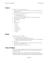
Page 10: ...Chapter 1 About the 7193 Printer 7193 Service Guide August 1998 4 ...

Page 11: ...may be ordered as options from NCR and will be shipped separately Wall mount kit for the printer Communication cable from host computer to printer Cash drawer with cables Removing the Printer 1 Remove the printer from the foam pack and open the receipt cover by pulling up on the front left corner 2 Remove the paper roll and test printout from inside the printer 3 Save all packing materials for fut...

Page 12: ...he following purposes To set variables for several printer functions see the sections for the various printer functions in Level 1 Diagnostics in the Diagnostics chapter To perform diagnostic tests see the sections for the various diagnostic tests in Level 1 Diagnostics in the Diagnostics chapter To set communication parameters for the RS 232C communication interface see RS 232C Switch Settings la...

Page 13: ...st computer and receive data online mode Switch 1 set to ON printer is in Level 1 Diagnostics setup mode If you want the printer to communicate with the host computer be sure switch 1 is OFF Use a paper clip or other pointed object to set the switch For additional information on the setup mode Level 1 Diagnostics see the Diagnostics chapter Note Some 7193 models may appear slightly different than ...

Page 14: ... 232C Communication On line Mode Default Level 1 Diagnostics Setup Mode 2 OFF ON DTR DSR Protocol Default XON XOFF Protocol 3 OFF ON Parity Disabled Default Parity Enabled 4 OFF ON Odd Parity Even Parity 5 6 5 OFF ON OFF ON 6 OFF OFF ON ON 19 200 Baud 9600 Baud Default 4800 Baud 1200 Baud Switch 4 is not used if the parity is disabled switch 3 set to OFF Note The following options are set with the...

Page 15: ...f Off Off ACK Handshaking On line Off Off Off Off Off Off Standard Busy Handshaking On line Caution The switches can also be used for setting other functions and tests Be careful when setting the switches for the Data Buffer settings that you do not accidentally change the settings for the other functions and tests Note The Data Buffer option is set with the printer in the setup mode See the table...

Page 16: ...O RS 485 Communication On line Mode Default On Level 1 Diagnostics Setup Mode DIP Switch 2 is always Off Address w Parity Address w o Parity Switch 3 Switch 4 Switch 5 Switch 6 3C BC Off Off Off Off 3D 3D Off Off Off On 3E 3E Off Off On Off 3F BF Off Off On On 40 40 Off On Off Off 41 C1 Off On Off On 42 C2 Off On On Off 43 43 Off On On On 44 C4 On Off Off Off 45 45 On Off Off On 46 46 On Off On Of...

Page 17: ...ash drawer The cash drawers are operated by software command from the host computer through the printer For additional information on the printer commands used by the host computer to activate the cash drawers see Appendix E Commands 1 Plug the cash drawer cables into the connectors on the printer The connectors are standard phone connectors 2 If only one cash drawer is used plug the cable into th...

Page 18: ...ne cable for communication and a separate cable for power Caution Be sure that all power is disconnected before connecting the cables 1 Turn off the host computer or unplug the power supply if it is plugged in 2 If the power supply is used plug the power supply cable into the printer first then plug the power cord into the power supply then into an outlet 3 Connect the communication cable to the p...

Page 19: ...7193 Service Guide Chapter 2 Installing the Printer August 1998 13 Parallel Models ...

Page 20: ...ing is working then beeps The On Line light green comes on indicating the printer is on line If the On Line light does not come on or either the On Line light or Paper Out light flashes see Troubleshooting later in this book 2 Press the On Line button again to take the printer off line Note On models receiving power from the host computer integrated the printer receives power when the communicatio...

Page 21: ...ress and hold the Paper Feed button while pressing the On Line button 3 Let go of the Paper Feed button once the printing begins The printer begins printing the data and character sets This can be given to a service representative if it appears there is a problem 4 To stop the test press the On Line button The On Line light turns off indicating the printer is off line 5 To return to the on line mo...

Page 22: ...Chapter 2 Installing the Printer 7193 Service Guide August 1998 16 ...

Page 23: ...hed to the bottom of the printer The rubber pads help the printer to fit snugly against the mounting bracket You will need a 1 4 inch drill bit and either a Phillips or standard screwdriver screws are combination Phillips and pan slotted 1 Using the bracket as a template mark and drill a hole for each plastic anchor 1 25 inches deep 2 Insert the anchors into the holes so they are flush with the wa...

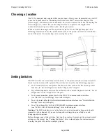
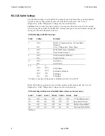
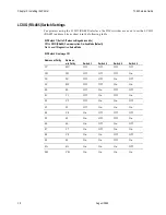
Page 24: ...Chapter 2 Installing the Printer 7193 Service Guide August 1998 18 ...

Page 25: ...emplate mark and drill a hole for each plastic anchor 1 25 inches deep 2 Insert the anchors into the holes so they are flush with the wall surface and screw the holder against the wall tightening the screws so that the plastic anchors expand and hold firmly in the wall Do not overtighten the screws Note You must unplug the power cord in order to place the power supply in the holder First take the ...

Page 26: ...Chapter 2 Installing the Printer 7193 Service Guide August 1998 20 ...

Page 27: ...sor timing is checked CRC check of the firmware ROM is performed external RAM is read failure causes level 0 diagnostics to stop the printer beeps once when the test is successfully completed Checks if paper is present Homes knife failure causes a fault condition Checks if receipt cover is closed failure does not interrupt the startup cycle When the last step is complete the Paper Feed button is e...

Page 28: ... the EEROM the DIP switches must be set back to the on line settings for the printer to operate The stored settings for the functions are printed with a dump of all resident characters during a print test See Testing the Printer in Chapter 2 Installing the Printer The default settings are set at the factory and are stored in the history EEROM Caution If you change the switch settings be sure they ...

Page 29: ...nter over and note what the current DIP switch settings are 3 Set the switches to the settings in the table you want for data reception errors and the data buffer Switch 1 Switch 2 Switch 3 Switch 4 Switch 5 Switch 6 Option On Off On Off Off Off for Data Errors1 2 On Off On Off Off On Ignore Data Errors2 On Off On Off On Off 4K Byte Data Buffer1 3 On Off On Off On On One Line Data Buffer3 1Default...

Page 30: ... 2 Turn the printer over and note what the current DIP switch settings are 3 Set the switches to the settings in the table that match the letter stamped on the heatsink in back of the printhead Printhead Setting Switch 1 Switch 2 Switch 3 Switch 4 Switch 5 Switch 6 Early 7193 Models Later 7193 Models On On On Off Off Off A A On On On Off Off On B B On On On Off On Off C C On On On Off On On D D On...

Page 31: ...r 2 1 Turn the power off 2 Turn the printer over and note what the current DIP switch settings are 3 Set the switches to the settings in the table that match the lines per inch setting you want as the default setting when the printer is powered up Switch 1 Switch 2 Switch 3 Switch 4 Switch 5 Switch 6 Default LInes per Inch On Off On On On Off 7 6 Factory Setting On Off On On On On 6 0 4 Turn the p...

Page 32: ...inter over and note what the current DIP switch settings are 3 Set the switches to the settings in the table that match the cut distance value you want the higher the number the longer the cut Switch 1 Switch 2 Switch 3 Switch 4 Switch 5 Switch 6 Cut Distance Value On On Off Off Off Off 0 On On Off Off Off On 1 On On Off Off On Off 2 On On Off Off On On 3 On On Off On Off Off 4 On On Off On Off On...

Page 33: ...carefully to avoid changing other functions Run the print test to see the current settings for this function See Testing The Printer in chapter 2 1 Turn the power off 2 Turn the printer over and note what the current DIP switch settings are 3 Set the switches to the settings in the table that match selection you want for the 7150 Response Mode on or off Switch 1 Switch 2 Switch 3 Switch 4 Switch 5...

Page 34: ...Emulates the NCR 7150 printer 4 Turn the power back on to enter the settings into the EEROM On remote models the On Line light green blinks 5 Turn the power off 6 Set the DIP switches to the former settings DIP switch 1 must be Off to return the printer to the on line mode Running the Data Scope Mode This test prints a Hex dump of all data sent to the printer 1 prints as Hex 31 A as Hex 41 and so ...

Page 35: ...ll commands and data sent from the host computer will be printed as Hex characters as shown in the following illustration Exit the Data Scope Mode 1 Turn the power off 2 Set the switches to the settings in the table Switch 1 Switch 2 Switch 3 Switch 4 Switch 5 Switch 6 On Off Off On Off Off 3 Turn the power back on to enter the settings into the EEROM and disable the Data Scope Mode On remote mode...

Page 36: ...ant Switch 1 Switch 2 Switch 3 Switch 4 Switch 5 Switch 6 Option On Off Off Off Off Off Sample Receipt1 On Off Off Off Off On Continuous Sample Receipt On Off Off Off On Off Character Sets1 On Off Off Off On On Continuous Character Sets2 1The Paper Feed button is used to begin the test 2Default 4 Turn the power back on to enter the settings into the EEROM On remote models the On Line light green b...

Page 37: ... Printhead too hot or voltages out of range The lights on the operator panel will signal when these conditions occur as well as indicate what state or mode the printer is in See Troubleshooting later in this book for more information Level 3 Diagnostics Level 3 diagnostics keep track of the following tallies and prints them on the receipt during the print test See the sample test printout in Testi...

Page 38: ...Chapter 3 Diagnostics 7193 Service Guide August 1998 32 ...

Page 39: ...e operator panel lights Operator Panel Lights The following chart describes the operator panel lights See Correcting Problems on the next page for more information about each of these conditions Light Condition Meaning Action Required Green On Printer is on line None Green Off Printer is unplugged or off line Connect printer to host or power supply and turn on Green Flashing Printer is in diagnost...

Page 40: ...ive five FETs Q1 Q8 Q9 Q13 Q14 Knife four FETs Q7 Q12 Q16 Q21 Thermal printhead one FET Q25 Cash Drawer 1 one FET Q5 Cash Drawer 2 one FET Q6 Speaker two FETs Q11 Q15 Caution Electro Static Discharge may damage the PC board Wear a grounded wrist strap and use a static mat or other ESD protected work surface whenever you work with the PC board If the resistance across any two pins is less than 1k o...

Page 41: ...n both ends Make sure the ground wire is properly connected Check that the host or power supply is getting power Receipt cover not fully closed Close and latch the receipt cover Cables within the printer are improperly connected to the PC board Make sure the cables in the printer are properly connected to the PC board ROM improperly positioned Check that the ROM is properly positioned DIP switches...

Page 42: ...ace the knife motor sensor Replace the knife motor Note When the knife test fails the printer continues to operate but does not cut paper Problem Possible Causes What To Do Thermal Printhead Over Under Temperature Operating printer in a room where temperature is above recommended temperature Adjust the room temperature Move the printer to a cooler location Continuous printing of graphics regardles...

Page 43: ...d Replace the PC board LED Does Not Come On Failed LED sensor Use the HEX FET test to see if the sensor is bad If so replace the LED sensor Printing Problems Problem Possible Causes What To Do Thermal Print is Light or Spotty Printhead resistance not properly set Adjust the printhead resistance See the Diagnostics chapter Paper roll loaded incorrectly Check that the paper is loaded properly See th...

Page 44: ...bleshooting 7193 Service Guide August 1998 38 time cleaning the printhead with cotton swabs and rubbing alcohol will not be of much benefit See Appendix B Ordering Paper and Supplies for the recommended paper grades ...

Page 45: ... the field Note Some 7193 models may appear slightly different than what is shown in the illustrations The procedures are the same for all models unless otherwise noted Getting Started Tools You will need the following tools to disassemble the printer Torx drivers 1 and 2 Posi drivers 1 mm hex driver for disassembly of optional knife Small flathead screwdriver Caution Before working on the printer...

Page 46: ...t to detach it from the printer at its hinges While removing the cover hold down on the printer with your other hand Removing the Platen Non Knife Units Only The platen can be replaced on non knife units only In some cases it may be better to replace the entire receipt cover Caution Be careful when removing the paper guide It may break If it does break you need to replace the entire receipt cover ...

Page 47: ...t mechanism or the stationary knife blade in the receipt cover need to be replaced on knife units both knife blades must be replaced Order the knife blade kit which includes the receipt cover See Appendix C Kits Removing the L Cover The L cover is held in place by three molded latches at its three corners 1 To release the rear latch push back on the rear wall of the cabinet with the printer facing...

Page 48: ...The print mechanism and board assembly come out of the cabinet together The first three steps apply to parallel models only Note The view in the illustration shows the printer from the bottom 1 On Parallel models only remove the parallel communication connector from the plate at the rear of the base by removing the two Hex screws 2 Remove the screw at the rear of the base to release the ESD shield...

Page 49: ... screw on the bottom of the printer Go slowly to preserve the screw hole 5 Turn the printer back over so it is right side up Caution Keep your hands away from the thermal printhead Touching the printhead will smudge it causing the print to degrade 6 Lift the front end of the assembly out of the cabinet by pushing on and lifting out the front of the print mechanism ...

Page 50: ...ugust 1998 44 Separating the Print Mechanism and PC Board Assembly 1 Remove the PC board assembly from the print mechanism by unscrewing the large 8 thread cutting screw on the bottom of the board using a P2 Posidrive screwdriver 2 Go slowly so as to preserve the screw hole ...

Page 51: ... gently tugging on the connector J1 sensor connector J2 motor connector for knife motor on knife unit J3 paper feed motor connector J4 cash drawer connector J7 4 pin connector for printhead ground 2 Remove the 30 pin ZIF connector J8 for the printhead a Carefully pry up the outer shell of the ZIF connector with a screwdriver b Remove the flat flex cable from the connector leaving the inner white c...

Page 52: ...he illustration 2 Carefully pry off the slotted drive arm separating it from the rotating blade Take care not to loosen or remove the gears 3 Unscrew the ground strap and remove it from the right hand side of the rotating blade 4 Unscrew both screws on the left side knife support using a 1 Posidriver and remove the left side knife support 5 Slide the rotating blade out of the right knife support N...

Page 53: ... 2 Slide the rotating blade into the right hand knife support 3 Replace the two screws in the left hand knife support securing it to the frame 4 Place the slotted drive arm on the right end of the rotating blade 5 Replace the set screw in the top of the slotted drive arm by using a 1 mm hex driver 6 Reattach the ground strap from the printhead to the right side of the rotating blade ...

Page 54: ... one side Take care to preserve the plastic tabs Caution Keep your hands away from the thermal printhead Touching the printhead will smudge it causing the print to degrade 3 Remove the left support by unscrewing the two screws Note You may find it easier to remove the knife motor before removing the printhead assembly See Removing the Knife Motor later in this chapter 4 Remove the printhead assemb...

Page 55: ...flex cable so that it can be slid into place without tearing 2 Slide the cable back down through the slot in the right bottom of the mechanism 3 Place the pin on the left side of the heat sink into its slot in the left side of the frame 4 Slide the right hand pin down into its slot 5 Replace the left support by screwing in the two screws 6 Snap the printhead into place and check to make sure it is...

Page 56: ...ed before the paper out swictch can be removed 1 Insert a screwdriver in the motor mounting hole and remove the screw holding the switch and then pull the switch from the print mechanism 2 Remove the cover open switch by removing the screw holding the switch and then pulling the switch off the print mechanism 3 Remove the knife home switch by removing the screw holding the switch and then pulling ...

Page 57: ...ead area facing you and replace the mounting screw 4 With the printhead area of the mechanism facing you place the knife home switch in position on the right hand side of the knife near the gears it fits on a molded mounting bracket in this area and replace the two screws holding it in position Removing the Paper Feed Motor 1 Remove the two screws holding the paper feed motor 2 Remove the paper fe...

Page 58: ... work with the PC board 1 Remove the ESD EMC shield from the PC board by taking out the self tapping screw from the front side of the board 2 Remove the two screws under the communication cable connector The shield then unfolds from the board and can be removed This step does not apply to models with the Parallel interface PC board Replacing the ESD EMC Shield Caution Electrostatic Discharge may d...

Page 59: ...crew and tighten slowly with a screwdriver Do not over tighten Reconnecting the Cables and Harnesses Reconnect the Printhead Cables See Separating the Print Mechanism and PC Board Assembly for more information The solder side of the PC board should be up when it is reconnected 1 Insert the 4 pin frame ground J7 into position in its connector 2 Lift up the locking outer shell of the larger ZIF conn...

Page 60: ... bottom screw and tighten gently Do not overtighten Finishing Up Replacing the L Cover See Removing the L Cover for more information 1 Attach the ground strap to the PC board 2 Position the cover taking care to align the buttons with the switches underneath 3 Push on the left corner until that latch snaps 4 Carefully push out on the inside back of the cabinet with your left hand while pushing down...

Page 61: ...ly separate in line power supply for models not receiving power from host Wall Mount Kit Cash Drawer Drivers Reliability Thermal mechanism 36 Million Lines Electronics 240 000 Hours of Ontime Knife 1 Million Cuts Environmental Conditions Operating Temperature 5 C to 35 C 40 F to 95 F models with no knife 5 C to 28 C 41 F to 82 F models with knife Operating Humidity 5 to 90 Condensation Condensatio...

Page 62: ... supply remote which can be purchased separately Power from Host Integrated Voltage 21 4 30 8 Vac 5 Volts for Logic Circuits Amps 2 Amps Maximum Current Draw Power from Power Supply Remote Voltage 24 Vdc 5 Volt Supply for the Logic Circuits Dimensions and Weight Height 119 mm 4 7 in Height with cover open 216 mm 8 5 in Width 165 mm 6 5 in Depth 187 mm 7 35 in Weight 1 3 kg 2 9 lbs ...

Page 63: ...6 Compressed Columns Character Pitch 15 2 Characters per Inch Standard 19 0 Characters per Inch Compressed Dot Density 152 Dots per Inch Line Spacing 7 6 Lines per Inch Character Cell 10 x 18 Dots Standard 8 x 18 Dots Compressed Print Modes Standard Compressed Double High Double Wide Upside Down Rotated Paper Diameter 83 mm Maximum 3 27 inches Paper Length 83 Meters 273 ft Paper Width 80 mm 2 mm 3...

Page 64: ...estrictions are ambient temperature the percentage of time measured against one minute of continuous solid printing and the amount of coverage Caution When the duty cycle approches the limits shown in the table the receipt printhead will heat up and shut down This may damage the printhead To avoid this problem do one or a combination of the following 1 Reduce the amount of coverage 2 Reduce the ti...

Page 65: ... Washington Church Road Miamisburg OH 45342 Voice 1 800 543 8130 toll free or local listing of Media Products sales office Ordering Other Supplies Contact your sales representative to order the supplies listed in the table Item Type Number Power supply with attached cable to printer and U S power supply cord 7193 K330 Power supply attached cable 7193 K301 Power supply cord to outlet United States ...

Page 66: ...Appendix B Ordering Paper and Supplies 7193 Service Guide August 1998 60 ...

Page 67: ...trap Screws Platen Bearing Platen with Gear Left and Right Knife Supports Grip Rings Cabinet Base Kit 189 9940606 Cabinet Base Self Adhering Foot Hook Fastener Loop Fastener Paper Feed Motor Kit Speed 189 9940830 models 7143 4xxx 5xxx only Stepper Motor Screw 189 9940607 all other models Stepper Motor Screw Knife Motor Kit 189 9940608 Stepper Motor Screw Cover Open Switch Kit 189 9940743 Micro Swi...

Page 68: ...0610 Micro Switch Screw Printhead Kit Speed 189 9940850 Printhead Screw Small Parts Kit 189 9940618 Left Knife Support Right Knife Support Knife Drive Arm Intermediate Gears Drive Gear Knife Grip Ring Ground Strap Screws Hardware Kit 189 9940619 Jack Cover Ground Strap Screws ...

Page 69: ...g and is located in the small cavity under the printer at the front It is not used with LCSIO RS 485 models that receive power from the host system RS 232C Connector The following illustration shows the RS 232C communication connector and pin assignments The cable is communication only It is not a power cable The connector is a 9 pin male D shell connector and is located in the hollow cavity under...

Page 70: ...Guide August 1998 64 RS 232C 25 Pin to 9 Pin Cable Diagram Note This information is provided for testing and troubleshooting only RS 232C 9 Pin to 9 Pin Cable Diagram Note This information is provided for testing and troubleshooting only ...

Page 71: ... the parallel interface is a 25 pin wired straight through cable The pin assignments are the same on either end of the cable This information is provided for testing and troubleshooting only LCSIO RS 485 Connectors The following illustrations show the LCSIO RS 485 communication connectors and pin assignments for printers powered from a host system and from a power supply The connector is in the ho...

Page 72: ...r 1 Connector Cash Drawer 2 Connector 1 Frame Ground Frame Ground 2 Drawer 1 Solenoid Drawer 2 Solenoid Remove jumper JPR4 to disable 3 Drawer 1 Status Switch Drawer 2 Status Switch 4 24 Volts to Solenoid 24 Volts to Solenoid 5 Drawer 2 Solenoid Remove jumper JPR3 to disable Drawer 1 Solenoid 6 Ground Status Switch Return Ground Status Switch Return RS 232C Printers Pin Number Cash Drawer 1 Connec...

Page 73: ...tion printer and the Epson TM T80 Thermal printer Any of the commands from either set may be used in any combination to program a host system to communicate with the 7193 unless otherwise noted Some commands listed here are not implemented in the 7193 they are identified as not implemented If received they are ignored and not sent to the print buffer as data Non legal commands are sent to the prin...

Page 74: ...0A Line Feed 0D Carriage Return 10 Clear Printer 14 n Feed n Print Lines 15 n Feed n Dot Rows 16 n Add n Extra Dot Rows 17 Print 19 1B 69 Full Knife Cut 1A 1B 6D Partial Knife Cut 1B 07 Generate Tone 1B 14 n Set Column 1B 20 n Set Character Right Side Spacing Not Implemented 1B 24 etc Set Absolute Starting Position 1B 32 Set Line Spacing to 1 6 Inch 1B 33 n Set Line Spacing to n Minimum Units 1B 3...

Page 75: ... and Cut Paper 1D 57 nL nH Set Printing Area Width Print Characteristics Commands These commands control what the printed information looks like and are listed in numerical order of their Hex codes Print Characteristics Commands Hex Code Command 12 Select Double Wide Characters 13 Select Single Wide Characters 1B 12 Rotate Characters Counter Clockwise 1B 16 n Select Pitch Column Width 1B 21 m Set ...

Page 76: ...Commands These commands send printer status information to the host system and are listed in numerical order of their Hex codes Printer Status Commands Hex Code Command 1B 75 0 Transmit Cash Drawer Status RS 232C Only 1B 75 n Request Alternate Status Parallel Only 1B 76 Transmit Printer Status Not Implemented for Parallel 1D 49 n Transmit Printer ID 1D 61 n Enable Disable Automatic Status Back 1D ...

Page 77: ...rinter Status Transmission Bar Code Commands These commands print bar codes HRI means Human Readable Interface The commands are listed in numerical order of their Hex codes Bar Code Commands Hex Code Command 1D 48 n Select Printing Position of HRI Characters 1D 66 n Select Pitch for HRI Characters Not Implemented 1D 68 n Select Height of Bar Code 1D 6B n etc Print Bar Code 1D 77 n Select Width of ...

Page 78: ...Appendix E Commands 7193 Service Guide August 1998 72 ...

Page 79: ...ication 64 disconnecting 45 power 12 reconnecting 53 Carriage return ignoring using 28 Cash drawer connector and pin assignments 66 ordering 60 Cleaning printer 3 Clearance around printer 6 Commands bar code 71 graphics 70 print characteristics 69 printer function 68 printer status 70 Communication cable ordering 60 Connecting cables cash drawer 11 communication 12 power 12 Connectors LCSIO RS 485...

Page 80: ...removing packing material 5 setting switches 6 testing printer 15 turning on printer 14 K Kits cabinet base kit 61 cover open switch kit 61 hardware kit 62 knife blade kit 61 knife motor kit 61 knife switch kit 62 paper feed motor kit 61 paper out switch kit 61 power supply 60 printhead kit 62 small parts kit 62 wall mount power supply 19 wall mount printer 17 Knife does not operate 36 setting par...

Page 81: ...n assignments 63 Power requirements 56 Power supply mounting on wall 19 ordering 60 wall mount kit 19 Power voltage 37 Print density receipt 58 Print mechanism disassembling 46 removing 42 replacing 53 54 Print test selections for printing 30 Printer cycles but does not print 35 mounting on wall 17 not functioning 35 Printhead over under temperature 36 print density 58 removing 48 replacing 49 res...

Page 82: ...0 shipped in box 5 wall mount kit 17 19 Switch settings 6 LCSIO address bits 10 Parallel 9 RS 232C parameters 8 Switches removing 50 replacing 51 T Tallies See level 3 diagnostics Testing the printer 15 Thermal paper ordering 59 requirements 59 suppliers 59 Thermal printhead See printhead Tools for disassembly 39 Troubleshooting FET s 34 knife does not operate 36 LED does not come on 37 operator p...

Page 83: ......

Page 84: ...BD20 1440 A Issue B 0898 NCR is the name and mark of NCR Corporation 1997 NCR Corporation Printed in U S A ...

Reviews: