1-12
Chapter 1: Product Overview
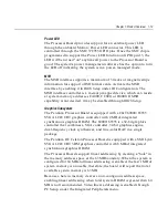
When the platform is in the Soft OFF state (refer to the Advanced Power
Management section that follows), receipt of a Wakeup Packet on the
LAN can return the system to the ON state, if this feature is enabled by
software.
1RWH
Due to limitations of the LAN controller and the OS, all features
described in the Network Device Class specification may not be
available.
100Base-T is wired identically to 10Base-T, except that the twisted pair
cable must be Category 5 and the hubs must permit 100 or 10/100
MB/s operation. Although 10Base-T will operate on Category 3 twisted
pair, or NCR "747" cable, an upgrade to Category 5 is required for
100Base-T.
A customer desiring to use the terminal in an existing 10Base-T
environment can do so and simply run at 10 MB. In order to upgrade to
100MB/s, Category 5 cable and 100 or 10/100 hubs must be installed.
NCR strongly recommends the use of Category 5 for all new cabling,
even if the customer initially intends to run only 10Base-T.
LED Indicators for Link Integrity (verifies cable and hub connection are
good) and LAN speed is provided on the Processor Board near the row
of connectors at the bottom of the e-box. The LED is ON (yellow) when
the speed is running at 100 MB/s.
Link Integrity is provided to the PC chipset to permit boot-up software
to verify the presence of the LAN connection. Software must allow 2
seconds after power-up in order for the Link Integrity signal to become
valid.
Wireless LAN Communications
Where a wired Ethernet connection is not desired a wireless LAN
adapter may be installed in the PCMCIA socket. This requires that the
PCMCIA daughter-card feature be installed. A wireless LAN used in
the terminal must meet the following requirements:
•
Integrated antenna that meets the requirements of PCMCIA (PC
Card) Extended Type 2 card definition (a maximum of 5-cm
additional length).
Summary of Contents for 7401 Web Kiosk
Page 1: ...NCR 7401 Web Kiosk Release 2 3 Hardware User s Guide 16436 NCR B005 0000 1254 Issue D...
Page 80: ...Chapter 2 Hardware Installation 2 21 2 Remove the Core Module from the Fixed Angle Mount 16397...
Page 183: ...3 74 Chapter 3 Setup...
Page 263: ...Appendix B Feature Kits B 55 11 Route the cables in the Wall Bracket as shown below 17359...
Page 302: ...B 94 Appendix B Feature Kits 17729 Pole Mount Wall Mount...
Page 326: ...B 118 Appendix B Feature Kits 2 Insert the end of the paper into the Paper Guide 16731...
Page 328: ...B 120 Appendix B Feature Kits 4 Remove the cut paper waste from the Presenter 16965...
Page 334: ...B 126 Appendix B Feature Kits 19050...
Page 367: ...Index 159...
Page 368: ...B005 0000 1254 September 2001 Printed on recycled paper...

