B-154 Appendix B: Feature Kits
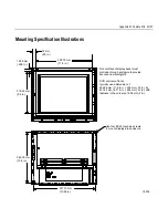
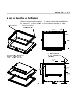
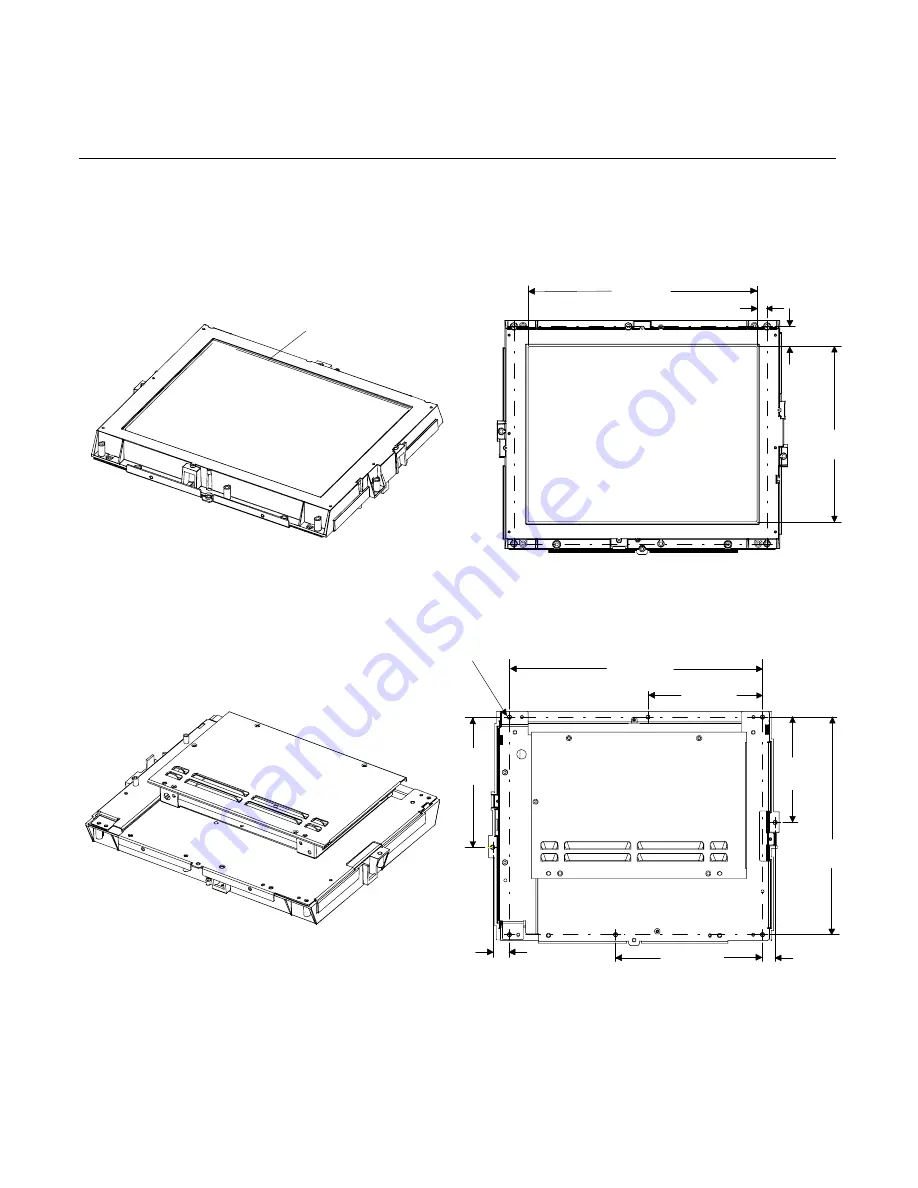
The following illustration shows the maximum allowable dimensions
for the display opening when the optional cosmetic bezel is not used.
19101
312.5 mm
12.305 in.
13.7 mm
0.540 in.
235.6 mm
9.275 in.
27.5 mm
1.083 in.
22.9 mm
0.900 in.
17.2 mm
0.678 in.
Gasket must meet inside surface of custom
application's display opening. This is to provide
a secure and watertight fit.
Use four #8-32 machine screws in the
corners of the unit to mount the display
into an enclosure. Six total screws may
be used for multiple mounting configurations.
345.4 mm
13.6 in.
156.2 mm
6.15 in.
292.4 mm
11.51 in.
141.6 mm
5.575 in.
175 mm
6.888 in.
200.7 mm
7.9 in.
Summary of Contents for 7401 Web Kiosk
Page 1: ...NCR 7401 Web Kiosk Release 2 3 Hardware User s Guide 16436 NCR B005 0000 1254 Issue D...
Page 80: ...Chapter 2 Hardware Installation 2 21 2 Remove the Core Module from the Fixed Angle Mount 16397...
Page 183: ...3 74 Chapter 3 Setup...
Page 263: ...Appendix B Feature Kits B 55 11 Route the cables in the Wall Bracket as shown below 17359...
Page 302: ...B 94 Appendix B Feature Kits 17729 Pole Mount Wall Mount...
Page 326: ...B 118 Appendix B Feature Kits 2 Insert the end of the paper into the Paper Guide 16731...
Page 328: ...B 120 Appendix B Feature Kits 4 Remove the cut paper waste from the Presenter 16965...
Page 334: ...B 126 Appendix B Feature Kits 19050...
Page 367: ...Index 159...
Page 368: ...B005 0000 1254 September 2001 Printed on recycled paper...

