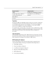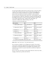
Chapter 1: Product Overview
1-19
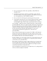
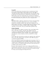
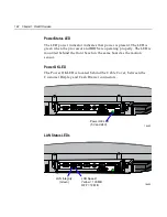
Power LED
The Processor Board provides support for an external power LED
through the onboard Motion/Power LED connector. This LED is
controlled through the SMC 37C935 GPIO pins. Once the SMC chip is
programmed to support the Power LED function on GPIO pin 13, the
LED will be turned "on" anytime all power to the Processor Board is
good. The system's power management software has the option to turn
the LED off indicating the system is in a power-managed mode.
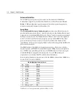
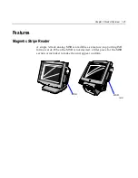
MSR
The MSR interface supports a maximum of 3 tracks of magnetic stripe
information for support of ISO format cards. Activate the MSR
interface by enabling it in BIOS Setup under IO Configuration. The
MSR interface controller is a memory-mapped device, which can reside
at system memory addresses CA000, CC000, or D0000. If MSR
capability is not desired, it may be disabled through BIOS Setup.
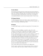
Graphics Subsystem
The Pentium Processor Board is equipped with a C&T 69000/65555
SVGA LCD/CRT graphics controller with 2 MB of integrated
synchronous graphics DRAM. The 69000/65555 is a 32-bit graphics
controller that combines a VGA controller, 32-bit graphics engine,
dual-frequency clock synthesizer, and true-color DAC in a single
package.
The Pentium III/Celeron Processor Board is equipped with a SMI Lynx
SVGA LCD/CRT 3DM graphics controller with 8 MB of integrated
synchronous graphics DRAM.
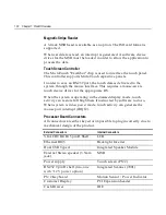
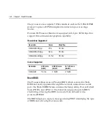
The Processor Boards support linear addressing by creating a "hole" in
the memory address space at the 63 MB boundary. When the system is
configured for 64 MB and linear addressing is enabled, the last 1 MB of
system memory is unusable; therefore, the board will report that total
available system memory is 63 MB.
Because a hole in memory creates a non-contiguous address space,
enabling linear addressing when total system DRAM is greater than 64
MB is not recommended. Video linear addressing is enabled through
PC Setup under the Integrated Peripherals menu.
Summary of Contents for 7401 Web Kiosk
Page 1: ...NCR 7401 Web Kiosk Release 2 3 Hardware User s Guide 16436 NCR B005 0000 1254 Issue D...
Page 80: ...Chapter 2 Hardware Installation 2 21 2 Remove the Core Module from the Fixed Angle Mount 16397...
Page 183: ...3 74 Chapter 3 Setup...
Page 263: ...Appendix B Feature Kits B 55 11 Route the cables in the Wall Bracket as shown below 17359...
Page 302: ...B 94 Appendix B Feature Kits 17729 Pole Mount Wall Mount...
Page 326: ...B 118 Appendix B Feature Kits 2 Insert the end of the paper into the Paper Guide 16731...
Page 328: ...B 120 Appendix B Feature Kits 4 Remove the cut paper waste from the Presenter 16965...
Page 334: ...B 126 Appendix B Feature Kits 19050...
Page 367: ...Index 159...
Page 368: ...B005 0000 1254 September 2001 Printed on recycled paper...

