Chapter 2: Hardware Installation
2-9
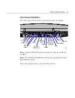
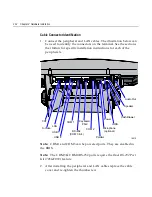
Cable Connector Identification
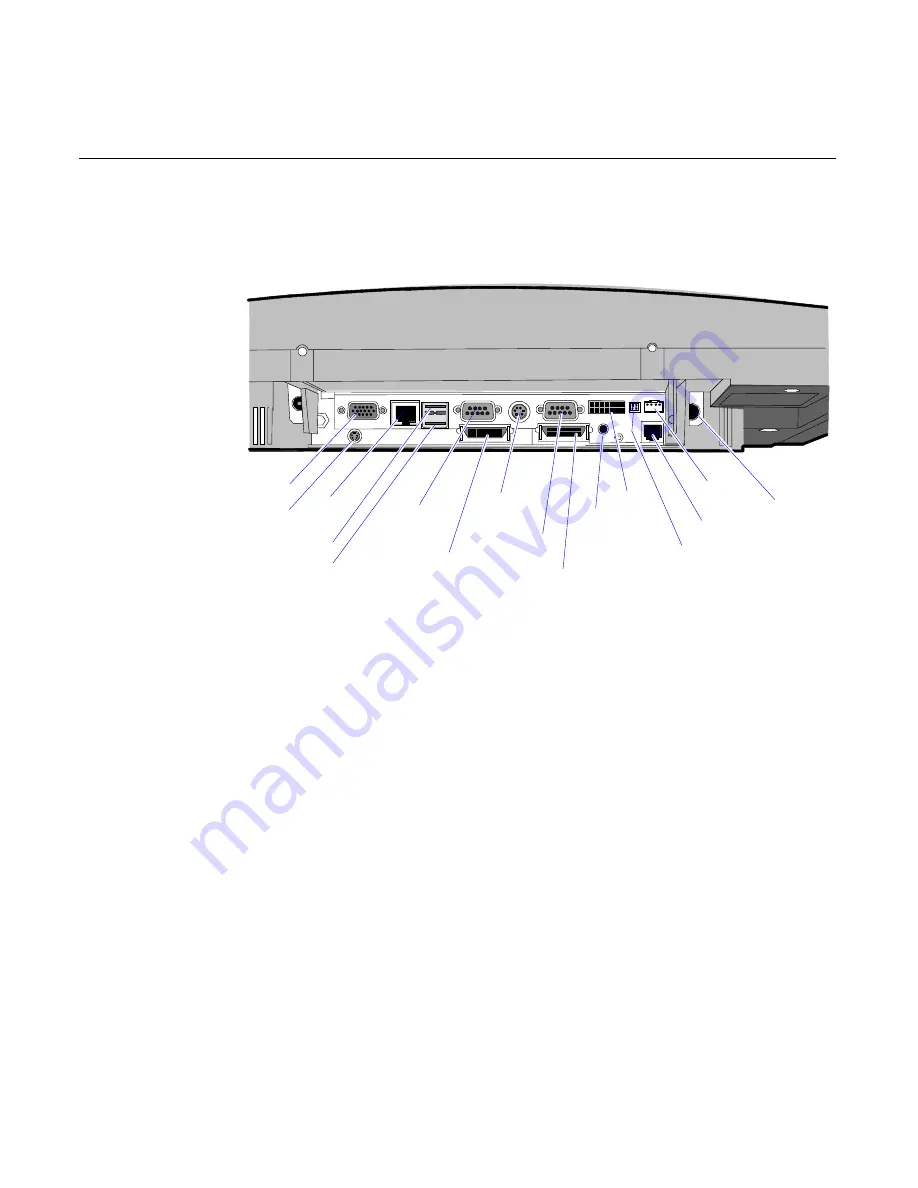
The cable connectors are located on the back of the Core Module.
18011
CRT
LAN
USB 2
COM 1
COM 2
Keyboard
PS/2
Parallel
Power
Audio Out
Cash Drawer
Speaker
S-Video
RS-232
(COM 3 & 4)
Microphone
(optional)
IRDA
USB 1
1RWH
COM1 and COM3 can be powered ports. They are enabled in
the BIOS.
1RWH
The COM3 & COM4 RS-232 ports require the Dual RS-232 Port
Kit (7454-F072) feature
After connecting the cables, reassemble the terminal.
Summary of Contents for 7401 Web Kiosk
Page 1: ...NCR 7401 Web Kiosk Release 2 3 Hardware User s Guide 16436 NCR B005 0000 1254 Issue D...
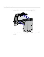
Page 80: ...Chapter 2 Hardware Installation 2 21 2 Remove the Core Module from the Fixed Angle Mount 16397...
Page 183: ...3 74 Chapter 3 Setup...
Page 263: ...Appendix B Feature Kits B 55 11 Route the cables in the Wall Bracket as shown below 17359...
Page 302: ...B 94 Appendix B Feature Kits 17729 Pole Mount Wall Mount...
Page 326: ...B 118 Appendix B Feature Kits 2 Insert the end of the paper into the Paper Guide 16731...
Page 328: ...B 120 Appendix B Feature Kits 4 Remove the cut paper waste from the Presenter 16965...
Page 334: ...B 126 Appendix B Feature Kits 19050...
Page 367: ...Index 159...
Page 368: ...B005 0000 1254 September 2001 Printed on recycled paper...

