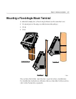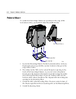
Chapter 2: Hardware Installation
2-37
1.
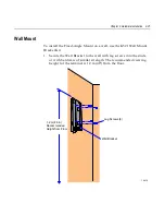
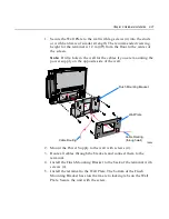
Secure the Wall Plate to the wall with lag screws (4) into the studs
or with hardware of similar strength. The recommended viewing
height for the terminal is 1.2 m (48") from the floor to the center of
the screen.
1RWH
Drill a hole in the wall for the cables if you are mounting the
power supply on the opposite side of the wall.
16684
Flush Mounting Bracket
Wall Plate
Cable Routing
Cable Routing
(through wall)
2.
Mount the Power Supply to the wall with screws (4).
3.
Route all cables through the brackets and connect them to the
terminal.
4.
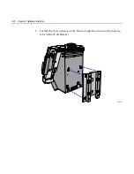
Install the Flush Mounting Bracket to the back of the terminal with
screws (4).
5.
Install the terminal to the Wall Plate. The bottom of the Flush
Mounting Bracket has slots that mate to locking tabs on the Wall
Plate. Secure the unit with the screw.
Summary of Contents for 7401 Web Kiosk
Page 1: ...NCR 7401 Web Kiosk Release 2 3 Hardware User s Guide 16436 NCR B005 0000 1254 Issue D...
Page 80: ...Chapter 2 Hardware Installation 2 21 2 Remove the Core Module from the Fixed Angle Mount 16397...
Page 183: ...3 74 Chapter 3 Setup...
Page 263: ...Appendix B Feature Kits B 55 11 Route the cables in the Wall Bracket as shown below 17359...
Page 302: ...B 94 Appendix B Feature Kits 17729 Pole Mount Wall Mount...
Page 326: ...B 118 Appendix B Feature Kits 2 Insert the end of the paper into the Paper Guide 16731...
Page 328: ...B 120 Appendix B Feature Kits 4 Remove the cut paper waste from the Presenter 16965...
Page 334: ...B 126 Appendix B Feature Kits 19050...
Page 367: ...Index 159...
Page 368: ...B005 0000 1254 September 2001 Printed on recycled paper...

