background image

3.


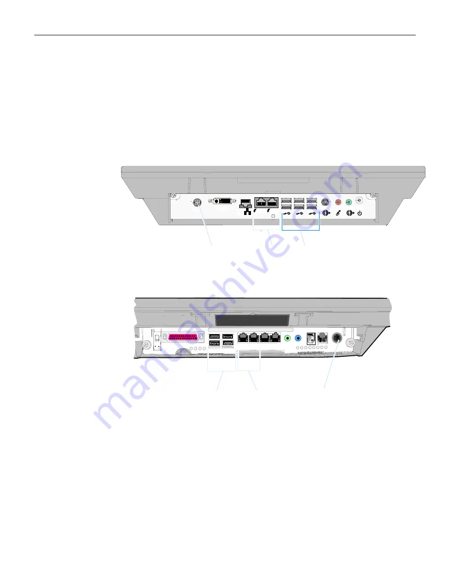
Remove


the


Cable


Cover


from


the


terminal


and


connect


the


cables


to


the


I/O


Panel.


Connect


the


Scanner


Cable


to


a


USB


connector.


Connect


the


MSR


Data


Cable


to


a


USB


connector.


Connect


the


MSR


Power


Cable


to


a


powered


RS

232


connector.


Which


ever


RS

232


port


is


used


it


must


be


set


to


12V.


See


Jumper


Settings


section.


7409 Connections 

27661a

RS232/B

RS232/A

A
B

Line Out 2

Line Out 1

Mic

Power

D V

 I - I

DC In

LAN

C
D

E
F

USB Ports

Terminal Power

RS-232 Ports


7404 Connections 

27660a

Mic Out Mic In

COM4 COM3 COM2 COM1

USB

USB

Parallel

On/Off

DC Power

Cash Drw

LAN

USB Ports

Terminal Power

Powered RS-232 Ports


4.


Replace


the


Cable


Cover.


5.


Close


the


Display


and


secure


it


with


screws


(2).


Summary of Contents for 7409-K360

Page 1: ...7409 K360 Fixed Angle Mount MSR and Bar Code Scanner Kit Instructions Issue A ...

Page 2: ...Revision Record Issue Date Remarks A Oct 2009 First issue ...

Page 3: ...duction This kit provides a Magnetic Stripe Reader and Bar Code Reader for the NCR EasyPoint Advantage 7404 and NCR SelfServ 60 7409 The assembly installs on the front of the 7409 K035 Fixed Angle Mount 27961 ...

Page 4: ...2 Installation Procedures 1 Hook the bottom of the bracket onto the bottom edge of the opening on the front of the Fixed Angle Mount 2 Secure the bracket with screws 2 27964 ...

Page 5: ... ever RS 232 port is used it must be set to 12V See Jumper Settings section 7409 Connections 27661a RS232 B RS232 A A B Line Out 2 Line Out 1 Mic Power D V I I DC In LAN C D E F USB Ports Terminal Power RS 232 Ports 7404 Connections 27660a Mic Out Mic In COM4 COM3 COM2 COM1 USB USB Parallel On Off DC Power Cash Drw LAN USB Ports Terminal Power Powered RS 232 Ports 4 Replace the Cable Cover 5 Close...

Page 6: ...te the jumper settings for the 7404 Motherboard Default settings are shown Powered RS 232 Ports COM3 COM4 23842 COM3 COM4 JP3 12 1 COM3 5V COM3 12V Pin 3 4 Pin 1 2 Pin 5 6 COM3 Ring Indicator COM4 5V COM4 12V Pin 9 10 Pin 7 8 Pin 11 12 COM4 Ring Indicator ...

Page 7: ...wered each port is capable of supporting up to 1 5 A Max and is protected with self healing poly fuse The default setting is Ring Indicator The power is selectable by JP4 26705c COMA COMB JP4 12 1 COMA 5V COMA 12V Pin 3 4 Pin 1 2 Pin 5 6 COMA Ring Indicator COMB 5V COMB 12V Pin 9 10 Pin 7 8 Pin 11 12 COMB Ring Indicator Default settings ...

Page 8: ...n S3 standby state USB Devices Capable of Waking the 7409 from an S3 State USB Keyboard USB Mouse Reasons for the Restrictions USB ports share UHCI host controllers in the Southbridge All external USB ports on the 7409 are powered by 5VSB and kept ON during S3 Standby Some USB peripherals are powered by the RS 232 port either 5V or 12V Ways Around the Issue Adhere to the Restriction Guidelines pro...

Reviews: