3-14 Chapter 3: Installing Optional Hardware Features
7.
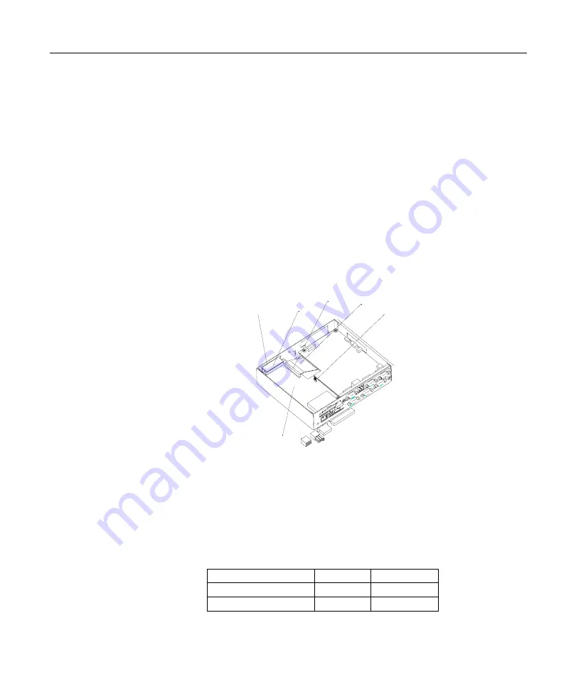
Replace the the Personality Board
* See disassembly procedure of each component in Chapter 2 of the NCR 7448
Hardware Service Guide.
Note:
After installing the Hard Disk Drive, AC Adapter for a printer will
not be located in the cabinet. Please locate the AC Adapter out of the cabinet.
8.
Install the Compact Flash I/F Board over the Main Processor Board.
Connect the Flat Cable for the Compact Flash I/F Board to the IDE (J1)
connector and connect the Flat Cable for Hard Disk Drive (if it is installed)
to the IDE (J2) connector on the Compact Flash I/F Board.
9.
Fix the Board with three screws on the Main Processor Board.
10.
Set the Jumper(J4) on the Compact Flash I/F Board to configure the
Compact Flash Card as a Master IDE device or a Slave IDE device.
If HDD exists, J4 position should be 1-2.(Default setting)
If HDD does not exist, J4 position should be 2-3.
J4 Definition Table
Compact Flash Card HDD
J4 Position
Slave Master
1-2
Master Slave
2-3
Flat cable to H D D
J2
J 1 Flat C able
C om pact Flash I/F board
J 4
Summary of Contents for 7448 Workstation
Page 1: ...NCR 7448 Workstation Release 1 4 Hardware User s Guide B005 0000 1202 Issue F...
Page 6: ......
Page 15: ...xiii...
Page 16: ......
Page 45: ...Chapter 2 Workstation Hardware Installation 2 7...
Page 48: ...2 10 Chapter 2 Workstation Hardware Installation...
Page 64: ...3 16 Chapter 3 Installing Optional Hardware Features 14 Connect the cable connectors...
Page 65: ...Chapter 3 Installing Optional Hardware Features 3 17 15 Attach the Hard Disk on the AC bracket...
Page 72: ...3 24 Chapter 3 Installing Optional Hardware Features...
Page 122: ...4 50 Chapter 4 Setup How to Perform MSR Test...
Page 152: ...4 80 Chapter 4 Setup...
Page 158: ...5 6 Chapter 5 Crisis Recovery 3 Click Next 4 Click Install...
Page 202: ...5 50 Chapter 5 Crisis Recovery...
Page 213: ...Appendix A BIOS A 11...
Page 232: ......


