background image

NCR 7454 Retail Terminal 

Release 2.2 

Hardware User’s Guide 

18004

NCR


B005-0000-1256 

Issue H 


Summary of Contents for 7454

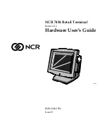
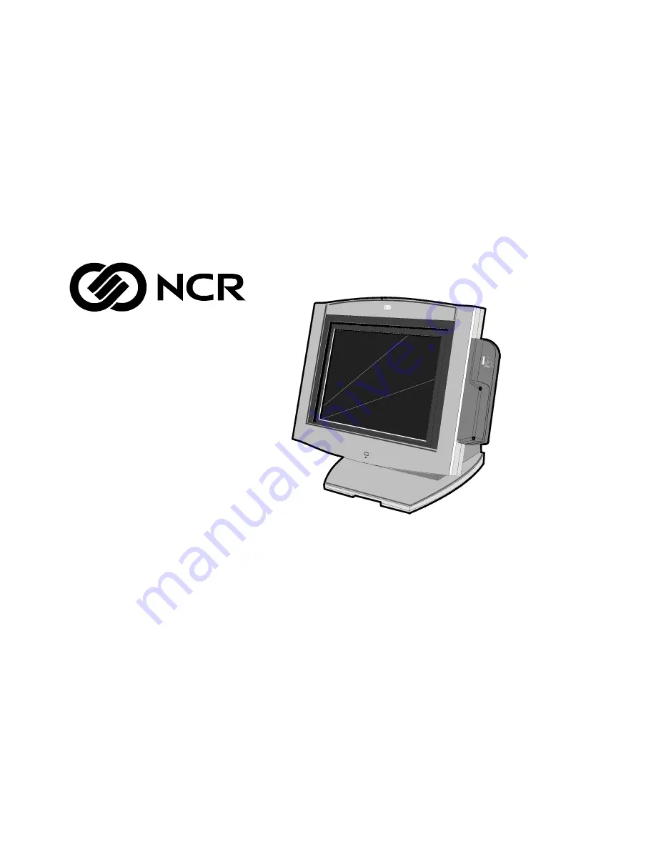
Page 1: ...NCR 7454 Retail Terminal Release 2 2 Hardware User s Guide 18004 NCR B005 0000 1256 Issue H...

Page 2: ...NIX is a registered trademark of The Open Group in the United States and other countries Symantic and Ghost are registered trademarks of Symantec Corporation in the United States and other countries b...

Page 3: ...ence This book is written for hardware installer service personnel system integrators and field engineers Notice This document is NCR proprietary information and is not to be disclosed or reproduced w...

Page 4: ...inal Site Preparation Guide B005 0000 1257 NCR 7454 Retail Terminal Software User s Guide B005 0000 1259 NCR 7401 7454 Retail Terminal Parts Identification Manual B005 0000 1072 NCR Retail Platform So...

Page 5: ...dule Descriptions 1 8 Processor Board 1 8 Processor Chip Set 1 8 Video Subsystem 1 9 Ethernet 10 100Base T LAN Communications 1 10 Wireless LAN Communications 1 11 Universal Serial Bus 1 13 Serial Por...

Page 6: ...agnetic Stripe Reader 1 27 Printer Options 1 28 2214 Printer 1 28 7158 Printer 1 29 7166 Printer 1 29 7167 Printer 1 30 7194 Printer 1 30 7196 Printer 1 31 7197 Printer 1 31 Other Integrated Devices a...

Page 7: ...on 2 7 USB Installation 2 8 2214 Printer 2 9 Installing a Remote Customer Display 2 10 5974 Remote Customer Display 2 10 5972 1100 Remote Customer Display 2 12 5973 International VFD Customer Display...

Page 8: ...mary 2 39 Out of Box Failures 2 40 Chapter 3 Setup Introduction 3 1 BIOS Versions 3 1 Entering Setup Without a Keyboard 3 1 Entering Setup Using a Keyboard 3 2 How to Select Menu Options 3 2 Restoring...

Page 9: ...on DOS 4 8 Gold Disk Contents 4 9 Microsoft Operating System License Agreements 4 9 Operating System Restrictions 4 10 Standby and Hibernate Mode Restriction 4 10 NCR 7454 32xx Win2000 Operating Syste...

Page 10: ...rocedures Introduction 5 1 Prerequisites 5 1 Updating Procedures 5 2 BIOS Crisis Recovery 5 5 Recovery Procedures 5 6 Cable Connector Pin Out Information 5 9 Chapter 6 NCR 7454 4x20 Customer Display I...

Page 11: ...Character Blink 6 12 Disable Character Blink 6 13 Move Cursor Left 6 13 Move Cursor Right 6 13 Move Cursor Up 6 14 Move Cursor Down 6 14 Move Cursor To Specified Position 6 14 Brightness Adjustment 6...

Page 12: ...as placed in a new document the 7454 Retail Terminal Hardware Service Guide B005 0000 1342 D June 01 Updated Connector Row Bracket illustrations updated serial port information and added Dual RS 232 P...

Page 13: ...t the 7454 supports a complete set of peripherals The major hardware features of the 7454 are a flat panel display with touch screen input and LAN connectivity plus optional magnetic stripe reader sca...

Page 14: ...cluded on a label on the back of the Core Module To view the label tilt the Core Module and remove the cable cover Note The serial number is repeated on the non MSR side of the Core Module NCR 7454 35...

Page 15: ...Flash BIOS not CMOS Four RS 232 ports two optionally powered 10 100BaseT Ethernet LAN chipset Wake on LAN support and RJ 45 port PC Audio with an internal mono speaker Sound Blaster 16 compatible audi...

Page 16: ...touch screen 2 5 hard disk Integrated Motion Sensor capable of waking up the terminal from a low power state Integrated Power Supply Reset switch which can be used to recover from a lock up condition...

Page 17: ...MB Compact Flash IDE Bus Cash drawers 2113 Cash Drawer modular 2189 Cash Drawer modular 2260 Cash Drawer modular Dual cash drawer cable 7454 Printers 7158 Thermal Receipt Impact Printer 7167 Thermal...

Page 18: ...unication to an NT server via standard protocols SLP terminal loading Local storage TCP IP networking and PXE loading Keylock for security X L R S Reset switch based security ISA and PCI Expansion slo...

Page 19: ...le 5972 5973 PS 2 KBD VGA POS Connector Bd USB Audio RS232 4 2 Optionally Powered Customer Display Parallel Cash Dwr 2336 K007 Ethernet 2336 K008 2113 7196 7166 2010 Coin Dispenser 7892 2214 Processor...

Page 20: ...r compatible audio capability Java Benchmark performance 1000 Caffeinemarks JIT compiled OS support to run Java Expansion capabilities for optional features and future requirements ISA PCI bus and USB...

Page 21: ...ctive matrix TFT 800x600 with 64 k colors 15 inch active matrix TFT 1024x768 with 262 k colors Support for the LCD integrated display is provided internally External support for SVGA monitors 800x600...

Page 22: ...asp Class retail_TPP Retail Customer Information Display User s Guide BD20 1431 B on the NCR Information Products web site at http www info ncr com eHome cfm Ethernet 10 100Base T LAN Communications T...

Page 23: ...run at 10 MB In order to upgrade to 100Mbps Category 5 cable and 100 or 10 100 hubs must be installed NCR strongly recommends the use of Category 5 for all new cabling even if the customer initially...

Page 24: ...cific extensions to the protocol that encourage users to stay with one supplier s equipment This also applies to wireless infrastructure and access points 802 11 does not govern this operation Mixing...

Page 25: ...rts The Summa POS Motherboard provides two RS 232 ports 9 pin D shell connectors Ports 1 and 2 directly on the Motherboard and supports two additional RS 232 ports Ports 3 and 4 require an optional ha...

Page 26: ...erature of the Processor exceeds safe levels Software can use this indication to slow or stop the system and or force a reset PCI Expansion Header A single expansion header is provided to support opti...

Page 27: ...aker sounds such as beeps and touch clicks are directed into the audio subsystem and are audible if speakers are connected Magnetic Stripe Reader A 3 track MSR head is available as an option The ISO a...

Page 28: ...mechanical design of the product External Connectors Internal Connectors VGA CRT RGB 15 pin D Shell LCD Ethernet RJ45 Back light Inverter Dual USB Type A Integrated Speaker Module External Stereo spea...

Page 29: ...e following features Dual Cash Drawer Support Cash Drawer Diagnostic Support Magnetic Stripe Reader Interface Motion Detector Touch Screen Interface An integrated retail specific feature of the proces...

Page 30: ...atus Solenoid A output active Solenoid A output inactive 1 Reserved Reserved Reserved 0 Cash Drawer s Status Drawer s open Drawer s closed Note Bits 2 and 3 are set to 1 by each device reset The cash...

Page 31: ...n for support of ISO or JIS format cards Activate the MSR interface by enabling it in BIOS Setup under IO Configuration The MSR interface controller is a memory mapped device which can reside at syste...

Page 32: ...EE000H EFFFFH 8 K System BIOS Reserved during boot ED000H EDFFFH 4 K Plug and Play ESCD Storage Area E0000H ECFFFH 52 K System VGA BIOS Reserved during boot BIOS Upgrades Flash memory makes distribut...

Page 33: ...either case the energy saving Standby mode can be initiated by a keyboard hot key sequence or a time out period set by the user When in Stand by mode the Processor Board reduces power consumption by...

Page 34: ...a user accessible contrast adjustment Software can set a default value after reading the Panel ID Display contrast changes with temperature LCD Adapter Board The signals from the LCD header on the Pr...

Page 35: ...ics of one or more components on the Inverter Board may have been compromised and the Inverter Board should be replaced If one or both Backlight tubes become disconnected or otherwise open circuited p...

Page 36: ...ty 5x7 characters It is available in a low profile or high post model 16949 The 7454 Retail Terminal also supports these remote customer displays NCR 7454 4x20 Customer Display This display uses the s...

Page 37: ...omer Display The NCR 5973 VFD Vacuum Fluorescent Display is an optional display device for the 7454 Retail Terminal The VFD is available in models that have a combination of Dark gray cabinetry Mounti...

Page 38: ...1 26 Chapter 1 Product Overview 16 High Post Mount 17198...

Page 39: ...Stripe Reader A single 3 track analog Magnetic Stripe Reader MSR is available as a feature supporting ISO and JIS format cards When the MSR is not desired a filler piece for the MSR section is includ...

Page 40: ...d brief description of the available printer options 2214 Printer The 2214 Printer is a thermal fiscal printer that can issue tickets and produce a journal Its power cord plugs into a 120 VAC power so...

Page 41: ...that you insert It receives its power from an external power supply can be connected through a USB or serial port and has a connector for cash drawers 17304c 7166 Printer The 7166 Printer is an extre...

Page 42: ...nter features a dual interface so it can connect to the host terminal either through a USB or RS 232 connector It receives its power from an external power supply and has a connector for cash drawers...

Page 43: ...nterface and a connector for cash drawers 17302 7197 Printer The NCR 7197 Printer is a fast quiet relatively small and very reliable multi function printer It prints receipts and two color printing Th...

Page 44: ...ed at the bottom of the enclosure Although not intended to be easily accessible the reset switch can be operated without removing covers or using any special tools 16454 Reset Switch Reset Procedure 1...

Page 45: ...r the cash drawers 24 V and VFD customer display 5 V and 12 V is supplied by the Enhanced Power Supply through the parallel connector Motion Sensor The terminal hardware can detect movement near the t...

Page 46: ...nsing logic on the Processor Board The user Power Status LED indicator shares this board Power Status LED The LED power indicator indicates that power is present The LED is green when the processor an...

Page 47: ...tal hazards Note The power supply automatically senses the proper AC voltage therefore only normal servicing access is required All power required to operate the base unit PCMCIA option and PCMCIA car...

Page 48: ...to the bottom of the Core Module The maximum output of the speakers is approximately 6 watts per channel USB RS 232 Port Server The USB RS 232 Port Server is an intelligent stackable expansion module...

Page 49: ...S 232 ports To add the ports install the Dual RS 232 Port Kit 7454 F072 as described in the Feature Kits appendix The following illustration shows the RS 232 Connector which is part of the Dual RS 232...

Page 50: ......

Page 51: ...ping packaging and visual checks made to verify the correct hardware configuration The system is then configured and any communication cables are connected Only after inspection should the power cord...

Page 52: ...tic electricity from your body before servicing the terminal If the power cord is replaced it must be replaced with the same type of cord with the protective shroud Do not route the power cord through...

Page 53: ...cable connectors are located on the underside of the Core Module under a cable cover Accessing the Cable Connectors 1 Tilt the display to access the cable connectors Cable Cover Thumb Screw 15968 2 Lo...

Page 54: ...base of the unit two thumb screws on bottom rear and use a tie wrap to secure the Ethernet cable to one of the provided molded cable tie holders on the base This should provide sufficient strain reli...

Page 55: ...ructions on installing each peripheral After installing the peripheral and LAN cables replace the cable cover and tighten the thumbscrew 19107 CRT LAN USB 1 COM 1 COM 2 Keyboard PS 2 Parallel Power Au...

Page 56: ...esponding printer owner s manual for illustrations of the connector locations Printer Type RS 232 USB 2214 Thermal Fiscal 7158 Thermal Receipt Impact Slip 7166 Thermal Receipt Impact Slip 7167 Thermal...

Page 57: ...on the bottom of the printer 16632a RS 232 Connector Power Connector Cash Drawer Connector 2 Connect the other end of the printer cable to one of the RS 232 non powered ports on the terminal 3 Connec...

Page 58: ...the bottom of the printer 16632b USB Connector Power Connector Cash Drawer Connector 2 Connect the other end of the printer cable to one of the USB connectors USB 1 or USB 2 on the terminal 3 Connect...

Page 59: ...Printer Interface Cable to the RS 232 Connector on the back of the printer 18543 RS 232 Connector Printer Interface Cable 2 Connect the other end of the Printer Interface Cable to an RS 232 port non p...

Page 60: ...ar 5974 Remote Customer Display 4x20 characters VFD 5972 1000 Remote Customer Display 2x20 characters VFD 5973 International VFD Customer Display 5974 Remote Customer Display 16670 1 Place the Display...

Page 61: ...lation 2 11 3 Secure the Mounting Plate with 4 screws provided 16671 Mounting Plate 4 Holes 0 40 mm 0 16 in Diameter 76 mm 3 in 4 Connect the Display Cable to the Customer Display port on the terminal...

Page 62: ...Remote Customer Display 16257 1 Place the Display Mount on the desired surface within 4 meters 13 feet of the host terminal 2 Determine if the cable should be routed down through the mounting surface...

Page 63: ...in 4 Connect the 5972 Display Cable to the Parallel I F Adapter Cable 16291a Customer Display 5972 Display Cable 497 0405676 4 M 1416 C278 0040 Parallel I F Adapter Cable 497 0411000 0 6 M 1416 C472...

Page 64: ...le 7 Plug the Power Brick into an AC outlet 5973 International VFD Customer Display 14528 4 Screws 1 Place the Display Mount on the desired surface within 4 meters 13 feet of the host terminal 2 Deter...

Page 65: ...ion 2 15 2 Secure the Mounting Plate with 4 screws provided 16258 Mounting Plate 4 Holes 0 40 mm 0 16 in Diameter 76 mm 3 in 3 Connect the 5973 Parallel Cable to the Customer Display port on the termi...

Page 66: ...lation Installing a High Post Integrated Customer Display The 7454 Integrated Customer Display supports four lines of twenty 5x7 characters This is the same display module that is used with the low pr...

Page 67: ...y Cover on the 5953 F022 Remote Table Top Mount does not support attachment of an integrated NCR 7454 4 x 20 Customer Display In order to mount an integrated display you need to install 5972 F039 whic...

Page 68: ...nnector has to be angled in order to make it though the openings Use care to not damage the wires 19949a Top Bracket Display Post Power Supply Cover 4 x 20 Integrated High Post Cable 2 Insert the post...

Page 69: ...ove the Integrated Display Bracket 2 screws b Connect the cable to the 2 x 20 VFD Assembly c Replace the Integrated Display Bracket 19948a 4 x 20 VFD Assembly Integrated Display Bracket Phillips PH Sc...

Page 70: ...ware Installation 6 Install the Nylon Hole Plug in the Power Supply Cover locking the post in place The slot permits the display to be rotated to personal preference 16948 7454 Customer Display Connec...

Page 71: ...crews 2 that secure the cover b Press in on both sides of the cover and lift it up in the back to remove it 20049 Screws 2 Press in on Both Sides 8 Install the Customer Display and Cover assembly onto...

Page 72: ...sh Drawer 1 Place the cash drawer in the desired location within cable length of the terminal 16269 2 Connect the cash drawer cable to the terminal cash drawer connector 15969c Cash Drawer Note The Ca...

Page 73: ...wer configuration with a Y cable 1416 C372 0006 1 Place the cash drawer in the desired location within cable length of the terminal 2 Connect the Y cable to the terminal cash drawer connector 16270 Du...

Page 74: ...2 24 Chapter 2 Hardware Installation Mounting the 7454 A Tilt Mount terminal can be installed on a flat horizontal surface or a flat vertical surface 16429 NCR Wall Mount Table Top Mount...

Page 75: ...uds or with hardware of similar strength The recommended viewing height for the terminal is 1 2 m 48 from the floor 16400 Wall Plate Wall Mount Adapter Plate Release Lever 2 Install the Wall Mount Ada...

Page 76: ...that are included in the disk image Complete the installation as follows 1 After the terminal reboots it will perform a disk check and then continue with the Windows 2000 installation 2 Enter the User...

Page 77: ...un the MicroTouch screen calibration Completing the OS Installation WinNT The system automatically reboots when the image recovery is complete and starts the software installation This installation al...

Page 78: ...e asked to reboot Answer No 2 At the User Information screen enter the User information This can be done using a keyboard or you can use the touch screen keyboard After entering the information press...

Page 79: ...allation 2 29 3 Run the MicroTouch screen calibration as described later in this chapter Completing the OS Installation DOS The system automatically reboots when the image recovery is complete and ope...

Page 80: ...want to use to logon to the client s a Open the User Manager Select the Windows Start button select Programs Administrative Tools Common and then Select User Manager b Select the User menu and then se...

Page 81: ...ter turn off the auto logon function e Select OK to close the Group Membership box f Select OK to create the account 2 Modify the Registry Select the Windows Start button and select Run 3 Enter regedi...

Page 82: ...32 Chapter 2 Hardware Installation 5 Create a new string value to permit auto logon for the default user Select the Edit menu select New and then select String Value 6 Name the new entry AutoAdminLogo...

Page 83: ...ct Modify Enter the value 1 for auto logon A value of 0 sets it to no auto logon 8 Select OK to set the value 9 Modify the DefaulUserName to contain the user ID that you want to automatically logon Wi...

Page 84: ...ltPassword 13 Edit the string value With DefaultPassword selected select the Edit menu and then select Modify Enter the value of the password of the default user from Step 1 The example below uses pas...

Page 85: ...OK e Select the C drive root directory Scroll down until you find the file named boot ini and select it f Open the File menu and then select Properties g Uncheck the box labeled Read Only and then sel...

Page 86: ...and installs the supporting drivers The drivers are located on the hard drive at C install i386 If for some reason they are not on the hard drive connect the terminal to a network and share a CD ROM d...

Page 87: ...Only use the Microcal DOS program the Touchware Control Panel Windows or Touchware icon on the Desktop XPe to calibrate the touch screen Microcal a Set the video resolution Go to the Tools menu Video...

Page 88: ...icrocal a Set the video resolution Go to the Tools menu Video Select 800 x 600 256 colors b Go to the Tools menu select Noise Check c Follow the instruction prompts Choose the frequency with the lowes...

Page 89: ...ctions in the order listed 1 Recalibrate 2 If re calibration is unsuccessful after two attempts then run the Noise check to change the frequency 3 If you are still not able to calibrate change the tou...

Page 90: ...reloaded drives Once a system is successfully installed all disk contents are the responsibility of the customer The customer is responsible for restoring operating system software and or customer spe...

Page 91: ...ns The Setup Menus in this chapter reference NCR 7401 7454 BIOS Version 1 5 0 4 Pentium and NCR 7401 7452 7453 7454 7455 BIOS Version 2 1 2 x Pentium III Entering Setup Without a Keyboard 1 Apply powe...

Page 92: ...the screen Entering Setup Using a Keyboard 1 Apply power to the terminal 2 Press the F2 key when the message at the bottom of the screen prompts you to do so Note Setup can also be entered from the Bo...

Page 93: ...To automatically reset all values to their default settings for the current screen press F9 The terminal will automatically load BIOS default CMOS values for boot up To reset all BIOS settings to thei...

Page 94: ...lly detected and the correct BIOS is automatically installed Main Values System Time variable System Date variable Legacy Diskette A 144 MV 1 25 MV 3 Legacy Diskette B Disabled IDE Primary Master Type...

Page 95: ...condary Slave Type None Memory Cache Enabled Cache System BIOS area Enabled Cache Video BIOS area Disabled System Memory 640 K Extended Memory 31744 K Power Savings Disabled Standby Timeout Off Auto S...

Page 96: ...s Monitoring Disabled Boot sequence 1 LANDesk Service Agent II 2 Hard Drive Continuous POST Disabled Advanced Values I O Device Configuration Local Bus IDE adapter Primary Serial port A Auto Serial po...

Page 97: ...ss Disabled Plug and Play No Reset Configuration Data No PS 2 Mouse Auto Large Disk Access Mode DOS Secured Setup Configurations No PCI Configuration ISA Graphics Device Installed No PCI PNP ISA UMB R...

Page 98: ...nterval Timer 1 Reserved Keyboard buffer full 2 Reserved Cascade interrupt 3 Serial Port 2 4 Serial Port 1 5 User available 6 Reserved Floppy 7 Parallel Port 1 8 Real Time Clock 9 NCR Motion Thermal i...

Page 99: ...e Description FECFF000 FECFF01B 27 LAN PXE ROM 100000 10000000 255 MB Extended memory F0000 FFFFF 64 K System BIOS EE000 EFFFF 8 K Main BIOS available as UMB ED000 EDFFF 4 K ESCD plug and play configu...

Page 100: ...3 10 Chapter 3 Setup...

Page 101: ...omatically installed Main Values Note An asterisk indicates a variable value based on system specification etc System Time System Date Legacy Diskette A Disabled Legacy Diskette B Disabled Primary Mas...

Page 102: ...Disabled Secondary Master None Type Auto Multi Sector Transfers Disabled LBA Mode Control Disabled 32 Bit I O Disabled Transfer Mode Standard Ultra DMA Mode Disabled Secondary Slave None Type Auto Mul...

Page 103: ...te Back Cache Base 512K 640 K Write Back Cache Extended Memory Write Back Cache A000 AFFF Disabled Cache B000 BFFF Disabled Cache C800 CBFF Disabled Cache CC00 CFFF Disabled Cache D000 D3FF Disabled C...

Page 104: ...ECP Fdc on Lpt Disabled Floppy Diskette Controller Enabled Serial Port C Enabled Mode Normal Base I O Address 3E8 Interrupt IRQ 5 Powered Auto Serial Port D Enabled Base I O Address 2E8 Interrupt IRQ...

Page 105: ...allel CD ROM Boot Disabled On board Intel PXE Enabled Lucent WaveLAN ROM Disabled WaveLAN PXE ROM Disabled Selectable ROM 7 Disabled Selectable ROM 8 Disabled Selectable ROM 9 Disabled Selectable ROM...

Page 106: ...ed ECC Config Disabled SERR Signal condition Multiple bit Default Primary Video Adapter AGP PCI PNP UMB Resource Exclusion C800 CBFF Available CC00 CFFF Available D000 D3FF Available D400 D7FF Availab...

Page 107: ...oot Mode Enabled Continuous POST Disabled Boot menu retry Keyboard Allow warm boot Disabled Security Values Supervisor Password Is Clear User Password Is Clear Set Supervisor Password Press ENTER Set...

Page 108: ...o Boot Values Intel R Boot Agent Version 4 0 17 Hard Drive ATAPI CD ROM Drive Removable Devices Exit Values Exit Saving Changes Press ENTER Exit Discarding Changes Press ENTER Load Setup Defaults Pres...

Page 109: ...Port 2 4 Serial Port 1 5 Serial Ports 3 and 4 6 Reserved Floppy 7 Parallel Port 1 8 Real Time Clock 9 NCR Thermal interrupt PII4 SMBus 10 Audio 11 LAN 12 Mouse available if disabled 13 Reserved Math...

Page 110: ...Range hex Size Description FECFF000 FECFF01B 27 LAN PXE ROM 100000 10000000 255 MB Extended memory F0000 FFFFF 64 K System BIOS EE000 EFFFF 8 K Main BIOS available as UMB ED000 EDFFF 4 K ESCD plug and...

Page 111: ...ient Software User s Guide for information about that procedure Prerequisites The following are required on the 7454 in order to perform an OS recovery using a CD Bootable CD ROM drive External 2336 K...

Page 112: ...t on the terminal 2 Connect the power connector to the CD ROM drive 18250 Parallel Connector Parallel Connector Power Connector Note The parallel port on the 7454 is the Customer Display port Therefor...

Page 113: ...35xx 36xx 37xx D370 0516 0100 D370 0565 0100 D370 0501 0100 D370 0500 0100 Discontinued D370 0445 0100 Note The 22xx models have been discontinued Contact NCR Product Manager for LPIN availability Con...

Page 114: ...rm Disk verification Answering Yes takes twice as long but is recommended If Yes is selected The Ghost software verifies write operations and handles bad FAT clusters The Ghost error file GHOST ERR is...

Page 115: ...cess remove the CD and press ENTER to reboot the terminal 18 Remove the CD during reboot for the OS to begin When system is restored reset the BIOS to normal defaults Completing the OS Installation Wi...

Page 116: ...the DOS window 3 Start the Network Setup Wizard 4 Select options to identify the network information for the terminal environment 5 Enter the Computer Description 6 Enter the Computer Name 7 Enter the...

Page 117: ...hat are included in the disk image Complete the installation as follows 1 When the terminal boots it enters the Windows setup routine Note When installing Win98 on terminals with early Processor Board...

Page 118: ...Complete the installation as follows 1 After the terminal reboots press Next at the Windows Setup screen 2 At the User Information screen enter the User information This can be done using a keyboard o...

Page 119: ...n or kiosk preloaded with a Microsoft operating system the application provider must follow certain license agreement guidelines Listed below are some of the major points of Microsoft s Embedded Softw...

Page 120: ...l without a keyboard or mouse the Windows 2000 Windows XP PRO and Windows XP Embedded OS Standby Mode and Hibernate Mode should be avoided These two modes place the hardware in a low power state which...

Page 121: ...inal over the network and restore the hard disk to the preinstalled state as shipped from the factory This enables installation of the following software Microsoft Windows 2000 Professional w SP2 Micr...

Page 122: ...ablished a FAT32 primary system partition that fills the entire drive Included necessary OS cab files in C Install Installed SP2 Exposed to both EM and EM video chipsets Exposed to a mouse so MicroTou...

Page 123: ...downloaded to the target terminal over the network and restore the hard disk to the preinstalled state as shipped from the factory This enables installation of the following software Microsoft Window...

Page 124: ...led SMI Control Panel 4 2 2 Installed Intel Proset utility Set virtual memory to 128 Enabled APM Set APM monitor shutoff to Never Set Enable PME in Intel Proset utility to Hardware Default Set color t...

Page 125: ...available version 3 02 Configures the following settings revisions Sysprep inf answer file and sysprep bat batch file created to Skip EULA Preinstall the Product ID Number PID Placed the Gold Drive Pa...

Page 126: ...e network and restore the hard disk to the preinstalled state as shipped from the factory This permits installation of the following software Microsoft Windows NT with SP6a Microsoft Internet Explorer...

Page 127: ...RunOnce to update the registry Established a 2gb FAT16 primary system partition Established a secondary NTFS partition that fills the remainder of the drive Included necessary OS cab files in C Insta...

Page 128: ...ogies 69000 Video driver CrystalWare Audio driver Intel EtherExpress software Intel PIIX Bus Master IDE drivers M Systems DiskOnChip 2000 driver not installed available Backpack CD ROM drivers not ins...

Page 129: ...e Part Number Date Created LPIN and Version in Registry under HKey Local_Machine Software NCR Gold Drive Windows Installer Version 1 1 installed Removes the following key from the registry as a curren...

Page 130: ...the network and restore the hard disk to the preinstalled state as shipped from the factory This permits installation of the following software Microsoft Windows 98SE Microsoft Internet Explorer 6 0 6...

Page 131: ...system partition that fills the entire drive Included necessary OS cab files in C Install Exposed to both EM and EM video chipsets Installed Intel Proset Utility Applied a Microsoft hotfix to replace...

Page 132: ...are Version 5 4 for Mouse Port software Chips Technologies 69000 Video driver Crystal Audio driver Intel 8255x based PCI Ethernet Adapter Intel PIIX Bus Master IDE drivers Backpack CD ROM drivers not...

Page 133: ...minal The bootstrap program di_intel bsd and disk recovery boot image di_intel bid are downloaded to the target terminal over the network and restore the hard disk to the preinstalled state as shipped...

Page 134: ...Product ID Number PID Placed the Gold Drive Part Number Date Created LPIN and Release in Registry under HKey Local_Machine Software NCR Gold Drive Added Userinfo exe to Start Menu to capture User Name...

Page 135: ...s sys file edited to include the following parameter Autoscan 2 IE5 MicroTouch version 5 4 Volume Line in set to 0 Scroll Bar Size set to 18 PCMCIA files updated Cbss vxd Pci vxd Pccard vxd Pcmcia inf...

Page 136: ...arting MS DOS 2 Follow the DOS screen prompts After each entry you are asked to confirm your input You can use 1 or y for Yes 2 or n for No 3 Enter No at the Disk verification question 4 Select which...

Page 137: ...16 2 GB FAT16 Win95 2 GB FAT16 Fill remainder as FAT 32 WinNT 2 GB FAT16 Fill remainder as NTFS Win98 Single FAT 32 partition N A Win2000 Single FAT 32 partition N A WinXPe Single NTFS partition N A N...

Page 138: ...4 28 Chapter 4 Operating System Recovery...

Page 139: ...bout that procedure Crisis Recovery In the event the BIOS becomes corrupt such as the result of a power failure during the BIOS Update procedure you can use the method discussed later in this chapter...

Page 140: ...Parallel Connector Parallel Connector Power Connector Note The parallel port on the 7454 is the Customer Display port Therefore if your terminal is configured with a Customer Display you must tempora...

Page 141: ...KPACK CD Starting MS DOS 12 Follow the screen prompts on the client to update the BIOS You can select two methods to run the update program Automatic BIOS Update update process runs unattended Note Yo...

Page 142: ...t the green window this indicates a successful update 14 Remove the CD and then press any key to reboot 13 When the system reboots press F2 at the screen prompt to enter Setup 14 In the Exit menu sele...

Page 143: ...e a no video state This procedure is not intended to be used for changing or upgrading an operational BIOS Required Hardware Part Number Part Name Use PC with at serial port Download BIOS 497 0408349...

Page 144: ...he Customer Display If the terminal is equipped with a Customer Display you must temporarily disconnect the display cable If the terminal is not equipped with a Customer Display then it is likely that...

Page 145: ...he Parallel I F Cable 16992 497 0411000 25 pin D Shell Receptacle 28 pin Sub Miniature D Plug Parallel Port Parallel Dongle 4 Boot the PC in the DOS mode with CD ROM support Note The PC must be runnin...

Page 146: ...A blue screen displays as the program runs showing the program progress followed by a green screen indicating a successful load PhoenixPhlash Status PRESS ANY KEY TO EXIT Flash memory has been success...

Page 147: ...ion Parallel Dongle 19513 25 Pin D shell Receptacle Viewed from wiring side 25 24 23 22 21 20 19 18 17 16 15 14 13 12 11 10 9 8 7 5 4 3 2 1 6 RS 232 Cable 19512 1 2 3 4 5 6 7 8 1 2 3 4 5 6 7 8 P1 P2 9...

Page 148: ...5 10 Chapter 5 BIOS Updating Procedures...

Page 149: ...ines the character sets and supported commands The NCR 7454 4x20 Customer Display is IEEE 1284 Compatible and supports Extended Capability Parallel ECP Viewing Area The characters are arranged in 4 ro...

Page 150: ...on the execution of the test An internal RAM test writes a varying numerical value to each RAM location The pattern must show that all RAM locations can be uniquely addressed All RAM will be written...

Page 151: ...Chapter 6 NCR 7454 4x20 Customer Display 6 3 Character Set Page 1 International...

Page 152: ...6 4 Chapter 6 NCR 7454 4x20 Customer Display Page 2 Japanese...

Page 153: ...Chapter 6 NCR 7454 4x20 Customer Display 6 5 Page 3 Code Page 850...

Page 154: ...tail VFD Command Interface The Retail VFD accepts two types of data display data and command data If a byte received from the host is any character except ESC 0x1B character it is processed as a chara...

Page 155: ...efault No 1B 0A Set Screen Save Walk No 1B 0B Turn On Screen Save No 1B 0C Disable Screen Save Feature No 1B 0D Enable Character Blink No 1B 0E Disable Character Blink Default No 1B 0F Move Cursor Lef...

Page 156: ...position the BUSY line is set to inactive conditions and all registers and variables are initialized Note that the screen is cleared during this command If a host needs previous data redisplayed the h...

Page 157: ...il one of the other state commands is performed Prior display data is saved and can be restored be sending the Turn On state 3 com mand Set Display State On Format 1B 05 Description This state is used...

Page 158: ...leaving the Low Power State the display is restored To leave the Low Power State one of the other state commands must be received This is the default state for the Retail VFD after power up Enable Cur...

Page 159: ...eled and the five minute timer is established Screen Save Blank removes power from the Retail VFD and does not refresh the display in the same manner as the Set Low Power On command At power up the ti...

Page 160: ...creen Save Blank and Set Screen Save Walk commands Enable Character Blink Format 1B 0D Description The blink attribute is the only modifier that is supported for the display character positions The at...

Page 161: ...yed whether the cursor is enabled and blinking or not After each character is displayed the firmware performs a logical Move Cursor Right command Move Cursor Right Format 1B 10 Description Moves the c...

Page 162: ...or is on the row 4 the cursor is moved to the same column on the row 1 The cursor location always indicates the position of the next character to be displayed whether the cursor is enabled and blinkin...

Page 163: ...2D 2E 2F 30 31 32 33 34 35 36 37 38 39 3A 3B 3C 3D 3E 3F 40 41 42 43 44 45 46 47 48 49 4A 4B 4C 4D 4E 4F Brightness Adjustment Format 1B 17 nn Range 01 nn 05 Description Adjusts the brightness of the...

Page 164: ...icator which indicates the length of the string that follows the string length indicator For example 1DH characters are sent after the string length indicator Note _ indicates a space character 20H Th...

Page 165: ...ay This means characters from multiple character sets may be on a display The default character set is Page 1 International Read Display Data String Format 1B 38 Returns 0x50 xxx xxxxx Where 0x50 is a...

Page 166: ...6 18 Chapter 6 NCR 7454 4x20 Customer Display...

Page 167: ...power 1416 C321 0030 006 8601012 Cord set United Kingdom plug with straight BM power 1416 C322 0030 006 8601019 Cord set Australian cable with straight BM power 1416 C323 0030 006 8601010 Cord set Int...

Page 168: ...K rectangular 1416 C411 0030 006 1012224 Power international 1416 C417 0040 497 0411815 Printer extender 9 pin female to 25 pin female 1416 C418 0040 497 0411816 Printer extender 25 pin male to 25 pin...

Page 169: ...sites 1 Select General Search 2 Select the Kit Instructions icon 3 In the Kit Title field enter the Kit Title Example Flash or In the Kit Number field enter the Kit Number Example 7454 K040 4 Select...

Page 170: ...Till 2 2189 K061 V001 497 0009210 Lid 2 2330 K340 V001 497 0416464 WaveLAN II Turbo 11 Mbs PCMCIA card for USA Canada 2330 K341 V001 497 0416466 WaveLAN II Turbo 11 Mbs PCMCIA card for Japan 2330 K35...

Page 171: ...g POS scale Canada 2756 K121 V001 497 0409421 Domestic power supply 2756 K122 V001 497 0409434 Y cable adapter mouse keypad 2756 K124 V001 497 0409422 International power supply 2756 K145 V001 497 040...

Page 172: ...01 497 0414901 10 MB Ethernet card with software license 5945 K010 V002 497 0414162 Cable 4 M RS 232 9 pin D shell 5945 K012 V001 497 0414163 Cable 8 M RS 232 9 pin D shell 5945 K020 V001 497 0412046...

Page 173: ...0 High fidelity speaker module 7401 K533 V001 497 0411713 Wall mount bracket tilt mount 7452 K183 V001 497 0415241 32 MB flash disk 7453 K002 V001 497 0407633 Modular cash drawer 2260 7453 K007 V001 4...

Page 174: ...tomer display bi directional in gray G105 7454 K454 V001 497 0427548 4x20 high post integrated customer display in charcoal gray CG01 7454 K455 V401 497 0427547 4x20 low post integrated customer displ...

Page 175: ...ting the OS Installation DOS 2 28 4 7 Completing the OS Installation Win2000 2 26 4 5 Completing the OS Installation Win95 2 28 4 7 Completing the OS Installation Win98 2 27 4 6 Completing the OS Inst...

Page 176: ...Ethernet 10 100Base T 1 10 F Finalizing the Installation after hardware installation 2 26 FLASH memory implementation 1 18 G Gold disk contents 4 8 H Hard disk drive 1 29 Hardware monitor 1 13 Hardwa...

Page 177: ...1 15 Description 1 8 Features 1 3 Processor chip set 1 8 R Remote customer display Installation 2 10 2 16 Reset switch 1 29 S Serial mouse Installation 2 34 Serial number 1 2 Serial ports 1 13 Setup...

Page 178: ......

Page 179: ......

Page 180: ...B005 0000 1256 Dec 2002 Printed on recycled paper...

Reviews: