background image

20

Site Preparation

7401 with 7949 Pedestal Mount

19289

457 mm
(18 in.)

457 mm
(18 in.)

203 mm

(8 in.)

203 mm

(8 in.)

171 mm
(6 3/4 in.)

400 mm
(16 in.)

1372 mm

(54 in.)

Spacer

7401-K580

7949-K035

7949-K033

Summary of Contents for EasyPoint 7401

Page 1: ...NCR EasyPoint 7401 Release 2 4 Site Preparation Guide 19797 NCR B005 0000 1255 Issue C...

Page 2: ...change specifications without prior notice All features functions and operations described herein may not be marketed by NCR in all parts of the world In some instances photographs are of equipment pr...

Page 3: ...n against risk of fire replace only with the same type and ratings of fuse Attention Pour pr venir et vous prot ger contre un risque de feu remplacer la fusible avec une autre fusible de m me type seu...

Page 4: ...recommended by NCR Corporation Caution DO NOT connect or disconnect a printer keyboard or any other terminal powered peripheral while the terminal is powered on Doing so may result in peripheral or s...

Page 5: ...ce personnel if the grounding instructions are not completely understood or if you are in doubt as to whether the product is properly grounded Use only 3 wire extension cords that have 3 prong groundi...

Page 6: ...tents of this document except where A customer has been notified that a full or partial consultant service is available and or that NCR will be willing to undertake a preliminary or final site survey...

Page 7: ...EasyPoint 7401 Hardware User s Guide B005 0000 1254 NCR EasyPoint 7401 Hardware Service Guide B005 0000 1341 NCR EasyPoint 7401 Interface Guide B005 0000 1405 NCR 7401 7454 Retail Terminal Parts Iden...

Page 8: ...vi Site Preparation...

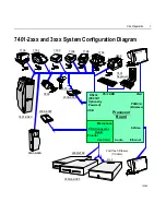
Page 9: ...tions 6 7401 2xxx and 3xxx System Configuration Diagram 7 7401 45xx System Configuration Diagram 8 7401 2xxx and 3xxx Kit Configuration Diagram 9 Physical Considerations 10 Operating and Service Clear...

Page 10: ...Cash Drawer 23 NCR 2189 Cash Drawer 23 NCR 2113 Cash Drawer 24 7453 K005 Cash Drawer 24 7156 Multifunction Printer 25 7194 Thermal Receipt Printer 25 7166 Thermal Receipt Impact Printer 26 7158 Therm...

Page 11: ...y K522 Universal Bracket 46 Considerations for Enclosed Installations 47 Ventilation Clearances 47 Thermal Test Points 48 Service Access 48 12 1 inch LCD No Cabinet Feature 7401 F752 49 Installation G...

Page 12: ...h Drawer Y cable 62 Ethernet 10 100 Base T 62 USB 63 External CD ROM Cable 63 External Parallel Cable 64 Power AC 64 Environmental Requirements 65 Barometric Pressure 65 Temperature 65 Humidity 65 AC...

Page 13: ...Site Preparation xi Revision Record Issue Date Remarks A Aug 00 First issue B Oct 01 Update model and kit changes C May 02 Updated to Release 2 4 Add EasyPoint 7401 45xx terminal...

Page 14: ...quipment or the substitution or attachment of connecting cables and equipment other than those specified by NCR The correction of interference caused by such unauthorized modification substitution or...

Page 15: ...International Radio Frequency Interference Statement Warning This is a Class A product In a domestic environment this product may cause radio interference in which case the user may be required to ta...

Page 16: ...omponent Label is attached to laser module inside the cabinet Laser Power The NCR EasyPoint 7401 scanner meets the following laser LED power requirements Class IIa CDRH Center for Devices and Radiolog...

Page 17: ...V 200 240 V 2 0 A 1 0 A 50 60 Hz NCR Corporation 1700 South Patterson Boulevard Dayton OH 45459 USA declares that the equipment specified above conforms to the referenced EU Directives and Harmonized...

Page 18: ...0 V 5 0 A 50 60 Hz NCR Corporation 1700 South Patterson Boulevard Dayton OH 45459 USA declares that the equipment specified above conforms to the referenced EU Directives and Harmonized Standards EU D...

Page 19: ...tect and correct after installation 7401 2xxx and 3xxx Models The 7401 2xxx and 7401 3xxx models are housed in an integrated compact cabinet and can be tilt mounted or fixed angle mounted These models...

Page 20: ...2 Site Preparation 7401 45xx Model 19889d...

Page 21: ...International English Power Required 80 110 240 VAC 50 60 Hz NCR Model 7401 X 1 X 80 Touchscreen Type 1 Self Service Model 2 Standard 3 Scanner 4 Keylock Cabinet 9 No Cabinet 01 2 Capacitive 8 Resist...

Page 22: ...Receipt Printer B005 0000 1170 NCR 7401 K580 Self Service Printer Owner s Guide B005 0000 1139 NCR 7401 K580 Self Service Printer Service Guide B005 0000 1140 NCR 7401 K580 Self Service Printer Parts...

Page 23: ...and laws including but not limited to electrical building safety and health are met Provide and install auxiliary power or other equipment as required Provide storage or service areas as required Meet...

Page 24: ...is recommended Refer to the Workstation and Peripherals AC Wiring Guide BSTO 2115 53 for store AC wiring requirements The AC outlet must be installed near the terminal and easily accessible to the ope...

Page 25: ...2189 2nd Cash Drawer Y Cable 7194 7890 7156 PS 2 KBD Processor Board VGA RS232 POS Connector Board USB Audio RS232 1 Optionally Powered Parallel Cash Dwr 7401 K580 2336 K007 Ethernet 2336 K008 2113 74...

Page 26: ...5xx Core Module USB 1 15 inch LCD Touch Screen PIII Motherboard Motorized Card Reader USB 2 Power Parallel Full Page Printer S Video MSR IRDA Speaker LAN Power Supply Speakers IRDA Receiver Swipe MSR...

Page 27: ...ion 9 7401 2xxx and 3xxx Kit Configuration Diagram 7401 3xxx 7401 2xxx K542 K533 F501 K530 K525 K523 F K590 F504 F511 F521 F101 F201 F502 F200 18318c 7401 w K590 K540 K543 K534 K535 K536 2336 K033 233...

Page 28: ...nsiderations This section presents the following 7401 information Operating and service clearance requirements Display mounting considerations 7401 and component dimensions Component weights Airflow r...

Page 29: ...mm 2 in Clearance for CRT tilt All units 153 mm 6 in Service clearance Left Side 7156 Printer 305 mm 12 in Clearance slip insertion All units 153 mm 6 in Service clearance Right Side CRT Display 64 mm...

Page 30: ...Fixed Angle Mount 12 1 Inch 370 mm 14 5 in 400 mm 16 in 450 mm 17 6 in 280 mm 11 in 400 mm 16 in 16420 120 mm 4 75 in 7401 32xx Fixed Angle Mount 15 Inch 18139 426 mm 16 75 in 391 mm 15 38 in 331 mm...

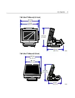
Page 31: ...Preparation 13 7401 22xx Tilt Mount 12 1 Inch 15970 380 mm 15 0 in 360 mm 14 0 in 370 mm 14 5 in 400 mm 16 in 7401 25xx Tilt Mount 15 Inch 18134 394 mm 15 5 in 425 mm 16 75 in 412 mm 16 25 in 35 mm 14...

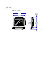
Page 32: ...14 Site Preparation 7401 22xx 12 Inch 370 mm 14 5 in 401mm 15 8 in 40 5 mm 1 6 in 53 4 mm 2 1 in 381 mm 15 0 in 312 mm 12 3 in 18200...

Page 33: ...Site Preparation 15 7401 25xx 15 Inch 14 3 mm 0 6 in 53 4 mm 2 1 in 392 1 mm 15 4 in 18201 391 mm 15 5 in 426 mm 16 8 in 338 mm 13 3 in 78 8 mm 3 1 in...

Page 34: ...1 88 in 393 7 mm 15 5 in 521 mm 20 5 in 620 mm 24 41 in 450 85 mm 17 75 in 125 mm 4 91 in 23 mm 0 91 in 90 mm 3 54 in 50 mm 1 97 in 152 mm 5 98 in 210 mm 8 27 in 7401 45xx w Keyboard Only The optional...

Page 35: ...Preparation 17 7401 K540 12 1 Inch w Keyboard Option 17296 550 mm 21 5 in 400 mm 16 in 400 mm 16 in 297 mm 11 63 in 7401 K543 Wall Mount Bracket w Wide Keyboard Shelf 19900 383 mm 15 06 in 97 mm 7 38...

Page 36: ...18 Site Preparation 7401 K580 590 w Self Service Printer 12 1 Inch 16698 180 mm 7 0 in 280 mm 11 in 880 mm 34 5 in 180 mm 7 0 in 530 mm 21 in 400 mm 16 in 370 mm 14 5 in...

Page 37: ...Site Preparation 19 7401 K580 590 w Self Service Printer 15 Inch 16698a 180 mm 7 0 in 330 mm 13 in 900 mm 35 in 180 mm 7 0 in 530 mm 21 in 426 mm 16 75 in 391 mm 15 5 in...

Page 38: ...20 Site Preparation 7401 with 7949 Pedestal Mount 19289 457 mm 18 in 457 mm 18 in 203 mm 8 in 203 mm 8 in 171 mm 6 3 4 in 400 mm 16 in 1372 mm 54 in Spacer 7401 K580 7949 K035 7949 K033...

Page 39: ...Site Preparation 21 7401 with 2336 K052 Pedestal Mount 19319 597 mm 23 5 in 597 mm 23 5 in 198 mm 7 8 in 203 mm 8 in 175 mm 6 9 in 1321 mm 52 in Optional Spacer 2336 K051 7401 K590...

Page 40: ...22 Site Preparation 7401 2336 K037 Pedestal Mount with Keyboard Shelf 19320 203 mm 8 in 597 mm 23 5 in 597 mm 23 5 in 198 mm 7 8 in 175 mm 6 9 in 1321 mm 52 in Optional Spacer 2336 K051 7401 K580 K590...

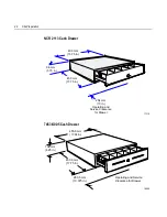
Page 41: ...awer 15414 121 mm 4 75 in 457 mm 18 in 457 mm 18 in 277 mm 11 in Operating and Service Clearance for Drawer NCR 2189 Cash Drawer 16676 133 mm 5 25 in 330 mm 13 in 18 25 in Operating and Service Cleara...

Page 42: ...10 96 mm 3 75 in 400 mm 15 75 in 450 mm 17 75 in 254 mm 10 in Operating and Service Clearance for Drawer 7453 K005 Cash Drawer 18038 455 6 mm 17 94in 108 mm 4 25 in 450 9 mm 17 75 in 263 5 mm 10 375 i...

Page 43: ...6 Multifunction Printer 11951a 242 mm 9 5 in 165 mm 6 5 in 119 mm 4 7 in 60 mm 2 375 in 264 mm 10 4 in 229 mm 9 0 in 7194 Thermal Receipt Printer 16492 130 mm 5 10 in 157 mm 6 20 in 85 mm 3 30 in 212...

Page 44: ...ation 7166 Thermal Receipt Impact Printer 171 mm 6 75 in 248 mm 9 75 in 330 mm 13 00 in 280 mm 11 00 in 17308 7158 Thermal Receipt Impact Printer 165 mm 6 50 in 336 mm 13 25 in 229 mm 9 00 in 305 mm 1...

Page 45: ...Site Preparation 27 7196 Thermal Receipt Printer 108 mm 4 25 in 140 m 5 50 in 146 mm 5 75 in 254 mm 10 00 in 17306...

Page 46: ...e 23 mm 0 9 in 155 mm 6 1 in 218 mm 8 6 in 16951 Note Allow 75 mm 3 in clearance in the back of the NCR 2336 K007 External CD ROM Drive for connector and cable clearance 2336 K008 USB RS 232 Port Serv...

Page 47: ...5 7401 3000 Fixed Angle Mount 9 6 21 5 7401 3500 Fixed Angle Mount 10 9 24 0 7401 2000 Tilt Mount 7 3 16 4 7401 K580 9 6 21 5 7401 K590 8 5 18 7 Scanner Module 4 0 9 0 2260 Cash Drawer 10 3 22 7 7453...

Page 48: ...ation Ventilation Clearance Leave the minimum clearances shown below for proper cooling conditions for the 7401 terminal NCR 7401 16423 76 mm 3 in 25 mm 1 in Minimum Vertical Clearance Minimum Horizon...

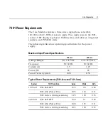
Page 49: ...for the power supply Maximum Input Power Specifications 120 volt 240 volt Voltage Ranges 90 136 VAC 198 257 VAC Frequency 50 60 Hz 50 60 Hz Current A 2 5 1 25 Power W 85 85 Power Factor typical 0 48 0...

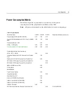
Page 50: ...in Soft OFF 1 0 120 0 12 System Idle at Windows Desktop Power On 1 3 156 0 15 Active during motorized card read 1 7 204 0 20 Active during typical print 2 5 300 0 30 Active maximum consumption 6 0 72...

Page 51: ...30 Current available for Peripherals Options 2 90 5 60 2 32 Peripherals subtract from line above LCDs TFT or DSTN 0 29 0 80 Integrated Display 4x20 VFD Powered from Parallel Port 1 00 Display 4x20 VF...

Page 52: ...al Port 0 50 1416 C643 0030 5945 Electronic Payment Device 497 0411818 0 50 1416 C634 4000 7194 7158 7196 Printers always require brick X 5992 Signature capture device X 5945 Electronic Payment Device...

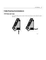
Page 53: ...Site Preparation 35 Cable Routing Considerations 7401 2xxx and 3xxx External cables can be routed out the back or the bottom of the Pedestal Mount 16424...

Page 54: ...36 Site Preparation Table Top Mount The internal cable connectors on the terminal are located on the underside of the Core Module under the Cable Cover Cable Cover Thumb Screw 15968...

Page 55: ...External cables can be routed out the back or the bottom of the terminal A 63 5 mm 2 5 in hole that aligns with the hole in the Table Top Mount must be cut in the table top when routing cables out the...

Page 56: ...e Preparation 7401 2xxx and 3xxx Mounting Considerations Viewing Height The terminal should be mounted approximately 1 2 m 48 in from the floor for proper use 16445 1 2 m 48 in Recommended Height from...

Page 57: ...Site Preparation 39 Terminal with K521 Wall Mount 19291 7 in 8 7 in 4 in 7 8 in K521...

Page 58: ...40 Site Preparation 17715 Wall Bracket Lag Screws 4 1 2 m 48 in Recommended Height from Floor K521 Wall Mount...

Page 59: ...Terminal with K521 Wall Mount and K530 Pole Straps 19283 1 2 m 48 in Recommended Height from Floor K530 Mounting Strap K521 Note K530 also includes pole mount adapter brackets used with K525 See illus...

Page 60: ...42 Site Preparation Terminal with Printer and K525 Wall Bracket 19282 Mounting Screw on both sides 15 35 in 33 70 in 3 75 in 7 80 in 15 35 in K530 Pole Bracket...

Page 61: ...Site Preparation 43 17593 Wall Bracket Lag Screws 6 1 2 m 48 in Recommended Height from Floor K525 Wall Mount...

Page 62: ...44 Site Preparation Mounting Screw on both sides 17735 K525 with K530 Pole Mount Straps...

Page 63: ...Site Preparation 45 Printer Only Mount K523 Wall Bracket Mounting Screw on both sides K523 12 00 in 4 in 7 820 in 14 00 in 19294...

Page 64: ...Preparation Terminal Only K522 Universal Bracket The terminal can be mounted on a flat surface or pedestal using the Universal Mounting Bracket 19295 Mounting Plate Flat Horizontal Surface Securing Sc...

Page 65: ...rements as illustrated and noted in the following pages Ventilation Clearances Verify that all clearance specifications are met as shown below 38 mm 1 5 in 76 mm 3 in 154 mm 6 in 356 mm 14 in 203 mm 8...

Page 66: ...oints are shown below 17316 Thermal Test Points Both sides of terminal Note For terminal servicing information refer to NCR EasyPoint 7401 Hardware Service Guide B005 0000 1341 Service Access The encl...

Page 67: ...2 The 12 1 inch LCD No Cabinet Feature F752 is purchased by customers who design their own enclosures to meet their specific needs This section provides information that must be considered when design...

Page 68: ...s connectors This feature comes with a motion sensor that is at the end of a 381 mm 15 in cable When using the motion sensor it must be mounted between 25 and 76 mm 1 to 3 in below the bottom of the...

Page 69: ...15 mm 12 88 in Front surface of display bezel must protrude through enclosure to provide secure and watertight fit NCR enclosure fronts typically use a dimension of 302 26 mm 11 9 in 254 mm 01 in by...

Page 70: ...horts the power supply and any other peripherals within the enclosure must be mounted securely and within reach of the display s connectors This feature comes with a motion sensor that is at the end o...

Page 71: ...mm 678 in 200 7 mm 7 900 in 175 mm 6 888 in 22 9 mm 900 in FRONT SURFACE OF DISPLAY BEZEL IF USED MUST PROTRUDE THROUGH ENCLOSURE GASKET MUST MEET INSIDE SURFACE OF CUSTOM APPLICATION S DISPLAY OPENIN...

Page 72: ...083 in 22 9 mm 0 900 in 17 2 mm 0 678 in Gasket must meet inside surface of custom application s display opening This is to provide a secure and watertight fit Use four 8 32 machine screws in the cor...

Page 73: ...The Core Module without either mount can be mounted flush against a wall The following shows mounting configuration and brackets 16683 Flush Mount w Power Supply Mounted on the Outside Wall Flush Mou...

Page 74: ...m 4 in 57 mm 2 25 in 17406 Wall Mount the Terminal Bracket Drill a hole in the wall for the cables if you are mounting the power supply on the opposite side of the wall 16684 Flush Mounting Bracket Wa...

Page 75: ...al should be mounted approximately 88 9 cm 35 in from the floor for proper use This provides for a keyboard height of approximately 94 cm 37 inches for stand up use and a viewing height to the center...

Page 76: ...enter to center measurements are shown in the following illustration When routing the cables out the bottom of the terminal a 63 5 mm 2 5 in hole must be cut in the table top that aligns with the hole...

Page 77: ...screws to mount the signage display The length of the screw is determined by the thickness of the signage mount plus 6 mm 0 25 in Do not use a screw that extends inside the cabinet more than 6 mm 0 2...

Page 78: ...ft Displays Parallel I F Cable adapter cable 497 0411000 1416 C472 0006 0 6 m 2 ft Power U S Straight 006 1009037 3 m 10 ft U S Twist lock 250 0023191 1416 C419 0030 3 m 10 ft Intl straight bm power 0...

Page 79: ...Site Preparation 61 Cable Type Cable Name NCR Part No Corp ID No Approximate Cable Lengths 497 0405945 1416 C286 0040 4 m 13 ft 7194 Printer 497 0411923...

Page 80: ...Dual Cash Drawer Y cable 15808 51 mm 2 0 in 16 mm 0 625 in Access Hole Diameters Cash DWR 1 Cash DWR 2 497 0409394 Ethernet 10 100 Base T 16298 19 mm 75 in 19 mm 75 in Access Hole Diameters Modular 8...

Page 81: ...15950 4 meter P1 P2 Type B USB 1 2 3 4 1 2 3 4 External CD ROM Cable 16959 To CD ROM Power Connector SMK 2 mm Plug To CD ROM Parallel Connector 497 0413011 0 6 M 1416 C464 0006 25 pin D Shell Receptac...

Page 82: ...OM Parallel Connector 497 0411000 0 6 M 1416 C472 0006 25 pin D Shell Receptacle 28 pin Sub Miniture D Plug 31 mm 1 25 in 57 mm 2 25 in Access Hole Diameters To 7454 Cust Display Port Power AC 15405 4...

Page 83: ...emperature changes exceed the temperature restrictions Temperature Parameter Restriction Operating 5oC to 45oC 41oF to 113oF dry bulb Storage 10oC to 50oC 14oF to 122oF three months Shipping 40oC to 6...

Page 84: ......

Page 85: ...ty is a customer responsibility The NCR Maintenance Agreement does not cover malfunction and or component failure as a result of power quality problems NCR accepts no liability for any such occurrence...

Page 86: ...or prevent any deficiencies Such systems must meet the following minimum requirements Be of the voltage limiting type and must self recover after passage of the transient Insert less than 5 ohms resis...

Page 87: ...C Cable Illustrations 62 Cable Routing Considerations 7401 2xxx and 3xxx 35 7401 4xxx 37 Cables 60 CD ROM Drive 28 Clearance Requirements 11 Communications 6 Customer Responsibilities 5 D Dimensions...

Page 88: ...9 20 21 22 Power requirements 31 Printer 7156 Thermal Receipt and Impact Slip Printer 25 7158 Thermal Receipt Impact Printer 26 7161 Thermal Receipt Printer 25 7166 Thermal Receipt Impact Printer 26 7...

Page 89: ......

Page 90: ...B005 0000 1255 May 2002 Printed on recycled paper...

Reviews: