background image


Chapter 3:  Hardware Installation  3-15 


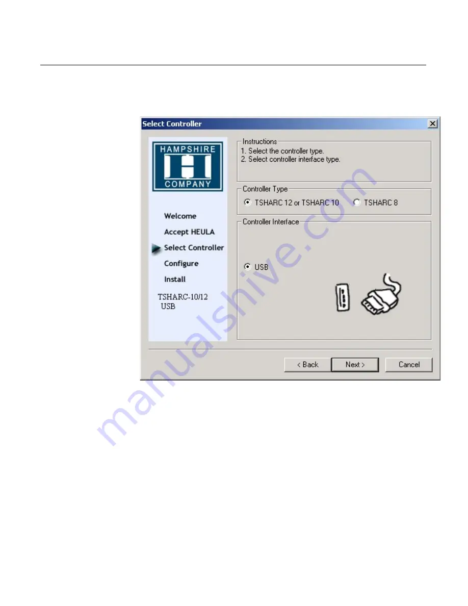
5.


Select


the


TSHARC 12


Controller


Type


and


USB


Controller


Interface


>


Next

.


6.


Setup


is


ready


to


install


>


Next


>


Finish


At


this


point


the


driver


is


loaded


and


functioning.


You


do


not


have


to


restart


your


system.


Summary of Contents for RealPOS 5953

Page 1: ...NCR RealPOS 5953 USB DynaKey Release 2 2 User Guide B005 0000 1457 Issue E...

Page 2: ...operations described herein may not be marketed by NCR in all parts of the world In some instances photographs are of equipment prototypes Therefore before using this document consult with your NCR re...

Page 3: ...D 1 4 Keylock Positions 1 5 Special PC Setup Keypad Layout 1 5 MSR 1 6 Speaker 1 6 Integrated 2 x 20 Customer Display 1 6 Chapter 2 Site Preparation Physical Environment 2 1 Operating Range 2 1 Storag...

Page 4: ...SB DynaKey 5964 K030 3 3 Installing a 5953 K023 Checkstand Mount 3 5 Connecting to the Host Terminal 3 10 Powering Up 3 10 Special Keypad Mode 3 10 Normal Operating Mode 3 13 Installing and Calibratin...

Page 5: ...NCR USB DynaKey Control Data Capture Registry Values 4 14 12 1 Inch USB DynaKey Video Drivers 4 16 Chapter 5 5953 USB DynaKey Migration Overview 5 1 Discussion 5 2 LCD 800x600 High Bright Long Life C...

Page 6: ...he Back Cover 6 7 Removing the MSR 6 8 MSR Cleaning Cards 6 9 Removing the Speaker Assembly 6 10 Removing the Touch Board Option 6 11 Removing the Controller Board 6 12 Removing the LCD 6 14 Replacing...

Page 7: ...v USB Connectors 6 23 Cables 6 24 DVI to DVI 6 24 Powered USB 12 V to 2 x 4 Locking Connector 6 24 DVI to CHAMP 6 24 DynaKey Cleaning Procedures 6 25 Cleaning the Glass 6 26...

Page 8: ...May 2003 Release 2 2 Added Touch Model D Dec 2003 Added new mount E Jan 2004 Added section on connecting to a standard PC Safety and Regulatory Information The NCR RealPOS 5953 conforms to all applic...

Page 9: ...s DynaKeys which are located beside the display The functions of these keys change depending on the software application appearing on the LCD The 5953 interfaces with the host terminal via two cables...

Page 10: ...htness CG1 5953 8301 12 1 USB SVGA Active Matrix Color Display Touch Screen No Mount No MSR No Cables High Brightness CG1 Features DVI Communications Industry standard video communications USB Communi...

Page 11: ...ications from the 5953 to the host terminal are through the Universal Serial Bus USB hub Cabinet Color The DynaKey is available in two color schemes Light Gray G11 Charcoal Gray CG1 External Standard...

Page 12: ...D are shown as follows Status Condition Green DynaKey power on Orange LCD in standby mode or see note below Red FPGA reporting an error condition Flashing red green DynaKey keypad in PC Setup mode See...

Page 13: ...ard input to prohibit use of normal functions R Retail Used when performing normal retail mode functions S Supervisor Used by the supervisor to provide highest level of workstation control in cases su...

Page 14: ...clicks but it can be programmed to sound tones under control of the application program The speaker is tied to the speaker control of the host terminal so that whenever the terminal speaker sounds so...

Page 15: ...nge Temperature 5 to 45 C Relative Humidity 10 to 90 Non condensing Atmospheric Pressure 3000 meters max Storage Range Condition Range Temperature 10 to 50 C Relative Humidity 10 to 90 Transit Range C...

Page 16: ...rt 5V 5 500 mA External USB Port 5V 5 500 mA External USB Port 5V 5 500 mA Touch Screen Board Optional 5V 5 100 mA Power Consumption Typical Maximum 16 0 W 19 2 W Cable Length Limitations Configuratio...

Page 17: ...Chapter 2 Site Preparation 2 3 Dimensions Standard Remote Table Top Mount 5964 K030 21139 470 mm 18 5 in 320 mm 12 6 in 255 mm 10 0 in...

Page 18: ...illustrated below The DynaKey can also be rotated right and left of center shown by approximately 90 degrees as well as tilted from a vertical position to approximately 45 degrees shown 19909 213 mm 8...

Page 19: ...Chapter 2 Site Preparation 2 5 There are two positions to install the post to the back of the DynaKey 19908 270 mm 10 75 in 200 mm 8 0 in 105 mm 4 13 in 140 mm 5 5 in...

Page 20: ...s may make it impossible to implement the lowest heights The height of the DynaKey should be adjustable along the y axis Ideally the DynaKey should be adjustable between 41 55 inches from the floor to...

Page 21: ...nches from the edge of the checkstand to the 7 8 9 key home row Most checkstands measure 24 26 inches wide In the event that the ideal adjustments are not feasible adjustability 12 18 inches from the...

Page 22: ...the DynaKey The DynaKey mount should permit rotation of 2 60 degrees about the x axis from vertical If it is impossible to achieve the entire tilt range 22 40 degrees is acceptable 20621 0 Standing Ey...

Page 23: ...9 Swivel Angle The DynaKey should be mounted directly in front of the cashier To accommodate off axis checkstands the DynaKey should swivel 37 degrees to the right and 37 degrees to the left of cente...

Page 24: ...2 10 Chapter 2 Site Preparation...

Page 25: ...by the appropriate safety agency for the country of installation Caution Use a grounding strap when installing this feature The DynaKey is fully assembled at the factory This section describes Serial...

Page 26: ...on the bottom edge of the DynaKey module 19940 Serial Number Label Cable Connector Access The cable connectors are located on the bottom of the 5953 assembly Tilt display to access the cable connecto...

Page 27: ...host terminal Mounting Options 5964 K030 Standard Remote Table Top Base G11 5964 K031 Standard Remote Table Top Base CG1 5953 K023 Checkstand Mount Each of the mounting options are discussed followed...

Page 28: ...ey DVI connector Connect external USB devices to the DynaKey USB connectors optional Connect the terminal Powered USB cable to the DynaKey Powered USB connector Note As an option the DynaKey can be po...

Page 29: ...t of the lower half of the Checkstand Base 17321 Checkstand Base Upper Half Thumbscrew Checkstand Base Lower Half Mounting Plate Side Cover 2 Slide the Side Cover off the lower half of the Checkstand...

Page 30: ...3 6 Chapter 3 Hardware Installation 5 Remove the Thumbscrew and the Front Cover from the Checkstand Base Upper Half 17322 Checkstand Base Upper Half Front Cover Thumbscrew...

Page 31: ...llation 3 7 6 Screw the Checkstand Base onto the back of the DynaKey 4 screws Note The back of the DynaKey has two sets of screw holes for mounting the base depending on user preference 21143 Base Pos...

Page 32: ...rdware Installation 7 Route the cables through the upper half of the Checkstand Base Install the Thumbscrew and the Front Cover Be sure to leave enough slack in the cables to permit easy tilting of th...

Page 33: ...be power from an external power brick 9 Route the cable s through the upper half of the Checkstand Base and install the Thumbscrew and the Front Cover Be sure to leave enough slack in the cable s to...

Page 34: ...to an AC power source 2 Turn the Keylock on the DynaKey to the Ex position 3 Power on the system Special Keypad Mode The BIOS setup routine requires keys that are not present in the regular DynaKey ke...

Page 35: ...er keys are pressed first pressing the 10 and 12 keys simultaneously will not put the DynaKey into the Setup Keypad Mode The status LED flashes red green to indicate that the keypad entered the Setup...

Page 36: ...g held down 3 Press the F2 key to put it into the BIOS configuration routine 4 Use the special keypad layout to run the system s BIOS Configuration routine Note The DynaKey Setup Keypad Mode is provid...

Page 37: ...neously This puts the keyboard back into its normal operating mode as shown Usually keys 22 23 and 21 25 are capped together by default 9 12 20069 8 7 4 5 6 1 2 3 0 CR F1 F2 26 27 28 29 30 31 32 33 1...

Page 38: ...g Download the Calibration software from the NCR website http www ncr com a At this site select Support b Under Related Items Services select Drivers and Patches Retail Support Files Retail Platform S...

Page 39: ...nstallation 3 15 5 Select the TSHARC 12 Controller Type and USB Controller Interface Next 6 Setup is ready to install Next Finish At this point the driver is loaded and functioning You do not have to...

Page 40: ...3 16 Chapter 3 Hardware Installation Calibrating the Touch Screen 1 Run the Hampshire Control Panel Run Programs Hampshire TSHARC Control Panel 2 Select the Calibration tab 3 Select Configure...

Page 41: ...3 17 The touch points default to 4 Point Calibration 4 points on the screen to touch The 7 Point is more accurate Choose which calibration you prefer and select OK Apply a Press the Calibration butto...

Page 42: ...Select Accept at the end of the settings if you are satisfied with the results If not repeat the process Touch Screen Options After the touch screen is calibrated adjust the features to meet your pref...

Page 43: ...ature The display has a time out function that causes the display to go blank after several minutes of inactivity The screen saving feature is controlled by NCR platform software integrated into the 5...

Page 44: ...USB PlusPower connection but does have a standard USB Type A connection and a DVI connection Connect the DVI cable to the DynaKey DVI and PC connectors Connect the USB cable to the DynaKey Powered USB...

Page 45: ...pressed providing auditory feedback to an operator of the keyboard This auditory feedback is optional The FPGA may be configured to make the sound or not to make the sound depending on the particular...

Page 46: ...ts During USB initialization all USB devices are required to enumerate Each device reports its data and ID to the host where the Host USB driver sends the report to the corresponding USB Device Driver...

Page 47: ...TONE FREQUENCY 0x21 TONE DURATION 0x22 TONE VOLUME 0x23 KEY_MATRIX_USAGE 0x31 NCR Proprietary HID Usages The report descriptors as emitted by the HID device should be consulted as the authority for t...

Page 48: ...k up table It is organized in FPGA Offset order and contains pairs of 8 bit usages one pair per key position Values of zero produce no usage report Two different usages produce two simultaneous usages...

Page 49: ...ide keys When you press a double high or double wide keycap the keyboard firmware sends the keycode for both keys When usages are the same only one keycode is sent Using the programmable key matrix fe...

Page 50: ...4 6 E1 3E LSh F6 2 0 32 3 E1 3C LSh F3 0 3 6 17 E0 3B LCtl F2 0 7 14 4 E1 3D LSh F4 0 4 8 16 0 5E 6 0 5 10 5 E1 3E LSh F5 0 5 10 5 E1 3E LSh F5 0 2 4 6 E1 3F LSh F6 0 6 12 0 0 0 4 7 78 7 E1 40 LSh F7...

Page 51: ...3 0 48 1 0 44 F11 6 3 102 25 0 58 Enter 3 1 50 0 0 0 4 0 64 26 0 3A F1 3 2 52 0 0 0 4 1 66 27 0 3B F2 3 3 54 0 0 0 5 0 80 28 0 3C F3 3 4 56 23 0 62 0 5 1 82 29 0 3D F4 3 5 58 0 0 0 7 0 112 30 0 3E F5...

Page 52: ...ction 5 3 86 0 0 0 5 4 88 15 0 5D 5 5 5 90 0 0 0 5 6 92 0 0 0 5 7 94 0 0 0 6 0 96 24 0 37 Period 6 1 98 34 0 51 Down Arrow 6 2 100 22 0 62 0 6 3 102 25 0 58 Enter 6 4 104 35 0 52 Up Arrow 6 5 106 18 0...

Page 53: ...frequency number given by the table of Note Numbers N and Frequencies freq listed in the following table Note Numbers and Frequencies Note N freq N freq N freq N freq N freq N freq A 0 28 24 110 48 4...

Page 54: ...392 70 1568 94 6272 118 25088 Ab 23 104 47 415 71 1661 95 6645 119 26580 Note The frequency f is given by the equation 12 N 2 5 27 f This table provides the full set of frequencies defined however the...

Page 55: ...report Each time SetClicks is invoked it reads Volume Frequency and Duration keyclick parameters from the registry If these parameters are not found in the registry default values are written to the...

Page 56: ...y default matrix of the specific product located Next the registry is read for replacement values within the Keyboard Matrix All registry values found in the appropriate registry key are replaced with...

Page 57: ...umber 3 A single keyboard usage to be installed for keynumber per key matrix section for PID_0321 DWORD 1Keywords are not case sensitive 2The Keywords frequency volume and duration and their values as...

Page 58: ...t a keyboard matrix map The application operates as a memory resident background process for a duration that may be specified on the command line If no duration is specified the application remains re...

Page 59: ...f seconds to remain resident waiting for additional devices to initialize 0 indefinitely 1 Keywords are not case sensitive and may be abbreviated to 3 or more characters Set USB Key Clicks Application...

Page 60: ...s manner the command line can optionally contain strings of the form keyword value where keyword is one of the defined parameters and value is an optional numeric value to be applied to that key The f...

Page 61: ...bility and connectivity The major advances are Standard Liquid Crystal Display LCD interface Full keyboard re programmability Added general purpose connectivity via on board port Flash programmable fi...

Page 62: ...dge 5953 USB Color 800x600 High Bright Long Life LCD Yes Yes LCD Interface NCR Proprietary Industry Standard DVI Touch Option Yes Yes Hot Plug No Yes POS Checkout style keyboard Standard PS 2 with 35...

Page 63: ...Key has an 800x600 High Bright Long Life Color LCD panel The USB and Wedge versions of the DynaKey employ similar panels with similar visibility and endurance characteristics LCD Interface The NCR 595...

Page 64: ...the USB 1 1 protocol which is a newer and different bit serial protocol that operates at either 1 5 or 12Mbps The keyboard operates at 12Mbps Furthermore each of these protocols includes a software la...

Page 65: ...nd the MSR and less widely used and thus customized HID devices such as the Keylock and Error Tone The USB DynaKey implements a standard seven port USB Hub internally which provides independent connec...

Page 66: ...ferent keys were pressed When the same two keys are capped together the firmware must know this and send only one message With the 5953 Wedge DynaKey this is accomplished by using firmware that senses...

Page 67: ...a programming steps Once the terminal has been set up with key assignments a replacement DynaKey will automatically receive the programmed key assignments Key assignments are sent from the registry wh...

Page 68: ...the host software In both DynaKeys placing the key in the L locked position disables the keyboard In the Wedge DynaKey the MSR and the external scanner port are disabled In the USB DynaKey the MSR and...

Page 69: ...r s application to be aware of the presence or absence of the MSR Scanner port The Wedge DynaKey contains an NCR proprietary RJ 45 connection for RS 232 based scanners This port has several technical...

Page 70: ...h the internal hub The Wedge DynaKey does not have this capability Smartcard Reader The USB DynaKey has been designed to accommodate an external or internal Smartcard reader that connects through USB...

Page 71: ...ulation Tool A GUI Active X control for Windows is available though non supported by NCR to simplify manipulation of the DynaKey keyboard re mapping registry entries Below is a screen shot of the GUI...

Page 72: ...alues the values have not yet been used to replace the current values stored in the registry The new values may be written to the registry using the Write Registry button This is the only action that...

Page 73: ...t assignments are shown and two new key usages may be selected from the drop down boxes Once selected the new value can be assigned using the OK button In the illustration below the top right key Key...

Page 74: ...5 14 Chapter 5 5953 USB DynaKey Migration...

Page 75: ...power down the terminal or PC and disconnect the terminal AC power cord Disconnect the cables from the workstation Caution To protect the internal circuitry from damage unplug the AC power cord and t...

Page 76: ...rovides general troubleshooting tips for the DynaKey If you experience a problem with your DynaKey please explore the possible solution options in this table before replacing any component in the syst...

Page 77: ...Ensure that magnetic stripe on card is up when swiped MSR harness loose or broken Ensure that the MSR harness is securely fastened to the DynaKey Controller Board and that none of the wires have pulle...

Page 78: ...Green LED Internal LCD cable loose Re seat the LCD harness at the DynaKey Controller Board and LCD ends Internal backlight harness loose Ensure that the backlight harness is securely fastened to the D...

Page 79: ...ssemble the DynaKey Warning Only properly trained personnel using proper grounding procedures should service the DynaKey Personal injury could occur or the DynaKey may be damaged Disassembling the Dyn...

Page 80: ...emoving the Remote Table Top Mount 2 Remove the Left and Right Housings from the mount one screw on each side 19907 Screws 2 3 Remove the screws 4 that secure the Remote Table Top Mount to the DynaKey...

Page 81: ...vice 6 7 Removing the Back Cover 4 Remove the Access Cover by applying pressure on the release tabs and then lifting up 19943a 5 Remove the 7 screws that secure the Back Cover and remove the cover 199...

Page 82: ...ervice Removing the MSR 6 Disconnect the MSR Cable J1 from the Controller Board 7 Remove the screws 2 that secure the MSR assembly 8 Push the plastic latching tab down and remove the MSR assembly Scre...

Page 83: ...SR module Note When reassembling the MSR notice there are actually two screws used to mount the MSR One was removed in the previous step 7 17193 MSR Screw MSR Cleaning Cards Part Part Number MSR Clean...

Page 84: ...6 10 Chapter 6 Hardware Service Removing the Speaker Assembly 10 Disconnect the speaker cable from Controller Board 11 Slide the speaker out of the metal fingers on the LCD Bracket 20062 Speaker...

Page 85: ...Chapter 6 Hardware Service 6 11 Removing the Touch Board Option 12 Disconnect the Touch Screen Cable 13 Remove the screws 2 that secure the Touch Board 20628 Touch Board Touch Screen Cable Screws...

Page 86: ...ontroller Board 14 Disconnect the cables on the Controller Board LCD Backlight Connectors LCD Connector Speaker Connector LED Board Connector Keypad Connectors MSR Connector Keylock Connector MSR 2005...

Page 87: ...dware Service 6 13 15 Remove the screws in the Controller Board and in the Connector Bracket 6 screws 16 Remove the board Note Verify all are cables free and out of the way prior to removal 20067 Scre...

Page 88: ...ardware Service Removing the LCD 17 Remove the screws 4 that secure the LCD Bracket to the Front Bezel 20629 Screws 4 18 Remove the LCD Bracket Assembly Verify that all cables are free before removing...

Page 89: ...o the LCD Bracket 20066 USB LCD Bracket Screws 4 LCD Replacing the Backlight After you remove the LCD from the frame you can replace the Backlight 1 Remove the screw that secures the Backlight 2 Caref...

Page 90: ...6 16 Chapter 6 Hardware Service Removing the Touch Screen 20 Gently lift the Touch Screen from the cabinet 20630 Touch Screen Note Clean any lint from the glass and LCD before reinstalling...

Page 91: ...Chapter 6 Hardware Service 6 17 Removing the Keypad 21 Remove the screws 3 that secure the Keypad to the Front Bezel 19924 Screws 3 22 Remove the keypad...

Page 92: ...Chapter 6 Hardware Service Removing the Keylock Adapter Assembly 23 To Remove Keylock assembly squeeze the plastic retainers and push the Keylock assembly out the front of the unit 16990 Plastic Retai...

Page 93: ...cing the Keylock assembly 1 Align the tabs and snap into place 2 Carefully route the wires through the bezel Re Assembling the DynaKey To re assemble the DynaKey module use the reverse order of the pr...

Page 94: ...er Board Connector Identification 19936 Keypad J2 J3 MSR J1 Keylock J6 Not Used J4 Single Port External USB J9 LED J5 LCD Backlight J7 J8 Speaker J10 Not Used J14 LCD J18 DVI J16 Dual Port External US...

Page 95: ...N c Unused 2nd DVI Link 6 DDC_CLK DVI DDC Clock 7 DDC_Data DVI DDC Data 8 n c No connection 9 CH1 of Channel 1 differential pair 10 CH1 of Channel 1 differential pair 11 GND TMDS Data 1 3 Shield Groun...

Page 96: ...CK of Clock differential pair 25 C1 ENAVDDMAG Magna ENA_VDD 26 C2 TFT_SEL2 Magna Panel ID2 27 C3 TFT_SEL1 Magna Panel ID1 28 C4 TFT_SEL0 Magna Panel ID0 29 C5 GND Ground 30 GND Ground Powered USB Conn...

Page 97: ...Chapter 6 Hardware Service 6 23 USB Connectors Pin Signal Name Typical Wiring Assignment 1 VBUS Red 2 D White 3 D Green 4 GND Black Shell Shield Drain Wire...

Page 98: ...0 m 1416 C723 0040 DVI 5953 DVI Terminal Powered USB 12 V to 2 x 4 Locking Connector 20059 497 0424838 1 0 m 1416 C757 0010 497 0424839 4 0 m 1416 C757 0040 Powered USB 5953 Powered USB Terminal DVI t...

Page 99: ...he following procedures 1 Disconnect the unit from the power outlet before cleaning 2 Use a soft cloth dampened lightly with a mild non abrasive soap water solution or 70 Isopropyl Alcohol 3 Gently wi...

Page 100: ...olvent Thinner Benzene Compressed Air Solvents Bleach Cleaning the Glass 1 Spray an ammonia based glass cleaner on a soft cloth and gently wipe the glass screen clean Warning Do not use any other type...

Reviews: